 Adobe Community
- Home
- After Effects
- Discussions
- Re: Trim paths controlling stroke size.
- Re: Trim paths controlling stroke size.
Copy link to clipboard
Copied
I'm making a trim paths to show a line and on the tip I have 2 circles that I also making with trim paths that are linked to the main line.
So the position and shapes are already as I want.
Now, is there a way to make the size of those balls start at Zero on the beggining and in the end and increase to the defined stroke size in the middle?
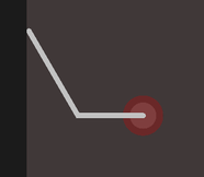
If I'd make a graph with its size it would be something like this:
Where the red area would be the stroke increasing/decreasing and the grey it would be the number defined on the stroke value.
It will aways start at 0 but, sometimes the trim path will stop at 40 or 60. Is there a way to account for its final value?
Is there a way to have this kind of result using expressions? I'd like to automate this part bc there's a lot of lines to do this.
 1 Correct answer
This may give you some ideas, depending on how you have things set up and what you're after exactly:
L = thisComp.layer("Shape Layer 1");
wMax = L.content("Shape 1").content("Stroke 1").strokeWidth;
pct = L.content("Trim Paths 1").end;
pctMax = pct.numKeys > 0 ? pct.key(pct.numKeys).value : 100;
pct < pctMax/2 ? ease(pct,0,10,0,wMax) : ease(pct,.9*pctMax,pctMax,wMax,0);Copy link to clipboard
Copied
https://helpx.adobe.com/after-effects/using/taper-shape-strokes.html
Correlating the actual timing to the taper is an entirely different exercise, though. One would likely fetch the keyframes of your dots and then remap the percentages to that in a manner like this:
mPoint=thisComp.layer("Point").transform.position;

mStart=mPoint.key(1).time;
mMid=mPoint.key(2).time;
mEnd=mPoint.key(3).time;

mDur=mEnd-mStart;
mDiff=mMid-mStart;

linear(mDiff,0,mDur,0,100);
Apparently this makes several assumptions about keyframes and how they are ordered in time. If there are more keyframes things won't work, which could be a problem if you draw complex shapes, in particular curves. In such a case one would have to use a loop which figures out what the last and its previous keyframe actually are and bass the calculation on that and one would potentially also need to decouple the actual path generation from the keyframes if you want the tapers to look even and not be tied to keyframe spacing...
Mylenium
Copy link to clipboard
Copied
Hi Mylenium, tks for the imput but it doesn't quite get me the result because my "mPoint" is actually a trimPahts and I got only 2 keyframes that goes from 0 to 100, sometimes 0 to 60.
Is there a way for example to add a slider to define the time transitio for the control?
Like if I could set it to 3 frames on the begginig and end, it might just do it. Might be a simpler?
Copy link to clipboard
Copied
As already mentioned this can be set up in a million ways and could be changed. The real question to me is how you want those arbitrary values to be defined. Apparently there would be no benefit if you just dial them in via sliders. Any expression-based solution needs a fixed frame of reference like the trim always being 100%, a fixed duration or speed at which the swirls draw, a fixed number of keyframes. If everything is variable there can never be a proper result. You'd have to explain how you envision it to work before anyone can sit down to create more elaborate code.
Mylenium
Copy link to clipboard
Copied
This may give you some ideas, depending on how you have things set up and what you're after exactly:
L = thisComp.layer("Shape Layer 1");
wMax = L.content("Shape 1").content("Stroke 1").strokeWidth;
pct = L.content("Trim Paths 1").end;
pctMax = pct.numKeys > 0 ? pct.key(pct.numKeys).value : 100;
pct < pctMax/2 ? ease(pct,0,10,0,wMax) : ease(pct,.9*pctMax,pctMax,wMax,0);Copy link to clipboard
Copied
Tks Dan, that's amazing as aways.
Not gonna lie, I don't understood the whole picture but it does fit my needs and I even figure out how to tweek it a bit.
Tks again.
Copy link to clipboard
Copied
Hey Dan, sorry to bother you again, but is there a way to detect witch path direction the path is using with an expression?
Like my strokes are all pointed to some other shape layer's path, and I could link them but if I have to revert the direction I'll have to change it manually on the "children", any way to link to those lille reverse direction buttons?
Copy link to clipboard
Copied
Just based on experimentation, this seems to get you to the switch:
L = thisComp.layer("Shape Layer 1");
p1 = L.content("Shape 1").content("Path 1")(1);
and a value of 3 seems to indicate that the "Reverse Path Direction" switch is on, and off seems to be 1 or 2, but I'm not sure why it's that way or what the implications are.
Copy link to clipboard
Copied
Tks Dan, I'll make some tests, really apreciatted the support.


