 Adobe Community
- Home
- FrameMaker
- Discussions
- Re: Drawing lines with ESTK is a nightmare
- Re: Drawing lines with ESTK is a nightmare

Copy link to clipboard
Copied
Friends, Romans, countrymen, lend me your ears! I come to bash Adobe [not plain Shakespeare]
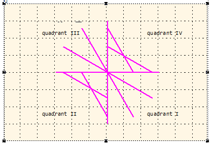
What strange mathematics is necessary to get the lines drawn as they should: all from a centre out at steps of 30°?
In the FM coordinate system y goes from top to bottom. I have found that the bounding box (aka dimensions) of the object is disconnected from the end points of the line. As You can see from the diagram below, created lines in quadrants II and IV are flipped up/down - after the drawing routine has been left!
How to cope with this strange happening!
// --- Create lines at all 30° angles - FM coordinate system in cm
#target framemaker
main ();
function main () {
var j, oDoc, oFrame, x0, x1, y0, y1, length, angle, oLine, oPoints = [];
CM = 1857713, pi = Math.PI;
oDoc = app.ActiveDoc;
oFrame = oDoc.FirstSelectedGraphicInDoc;
if (!oFrame.ObjectValid()) {
Alert("Select an anchored frame and try again.", Constants.FF_ALERT_CONTINUE_WARN);
return;
}
for (j= 0; j < 8; j++) {
length = 3;
angle = pi/4 * j; // 0, 30°, 60° … 330°
x0 = 6;
y0 = 4;
x1 = x0 + length * Math.cos(angle);
y1 = y0 + length * Math.sin(angle);
oLine = CreateLine (oDoc, oFrame, x0, y0, x1, y1);
oPoints = oLine.Points; // after drawing lines in quadrants II and IV are flipped up/down!
$.writeln ("b xo/y0 = " + oPoints[0].x/CM + "\t" + oPoints[0].y/CM );
$.writeln ("b x1/y1 = " + oPoints[1].x/CM + "\t" + oPoints[1].y/CM );
}
} //--- end main
function CreateLine (oDoc, oFrame, x0, y0, x1, y1) {
// x, y are the location of endpoints [cm]; FM-coordinate system!
var j, oLine, oPoints = [], oPoint=[], width, height,
CM = 1857713, FRMAKER5819 = 8192;
oPoints.length = 0;
oLine = oDoc.NewLine(oFrame);
oPoint0 = new Point(),
oPoint0.x = x0*CM; oPoint0.y = y0*CM;
oPoints.push(oPoint0);
oPoint1 = new Point(),
oPoint1.x = x1*CM; oPoint1.y = y1*CM;
oPoints.push(oPoint1);
width = x1 - x0;
height = y1 - y0;
oLine.Width = Math.abs(width)* CM;
oLine.Height = Math.abs(height)* CM;
if (Math.abs(width)* CM < FRMAKER5819) {oLine.Width = FRMAKER5819};
if (Math.abs(height)* CM < FRMAKER5819) {oLine.Height = FRMAKER5819};
// --- quadrants in FM coordinate system ---------
if (x0 <= x1 & y0 <= y1) {$.writeln ("\n------------ quadrant I");
oLine.LocX = x0 * CM; oLine.LocY = y0 * CM;
}
if (x0 > x1 & y0 <= y1) {$.writeln ("\n------------ quadrant II");
oLine.LocX = x1 * CM; oLine.LocY = y0 * CM;
}
if (x0 > x1 & y0 > y1) {$.writeln ("\n------------ quadrant III");
oLine.LocX = x1 * CM; oLine.LocY = y1 * CM;
}
if (x0 <= x1 & y0 > y1) { $.writeln ("\n------------ quadrant IV");
oLine.LocX = x0 * CM; oLine.LocY = y1 * CM;
}
$.writeln ("a xo/y0 = " + oPoints[0].x/CM + "\t" + oPoints[0].y/CM );
$.writeln ("a x1/y1 = " + oPoints[1].x/CM + "\t" + oPoints[1].y/CM );
oLine.BorderWidth = 0.05*CM; // Stroke-width
oLine.Color = oDoc.GetNamedColor("Magenta");
//$.bp(true);
return oLine;
} //--- end CreateLine
The constant FRMAKER5819 is there to cope with the error described in the respective bug report.


 1 Correct answer
Eventually I managed to implement the flipping. Now the function works as expected - thanks to the very important hint from Markus.

With this script
.../* CreateLines.jsx ====== UTF-8 ===================================================================
Create ines in various angles
Copyleft 2018 Klaus Daube, Zürich, Switzerland, klaus@daube.ch
History 2018-12-19 final solution with two bypasses
*/ ; // ======================================================
 10
Replies
10
10
Replies
10

Copy link to clipboard
Copied
Moved to FrameMaker Scripting.

Copy link to clipboard
Copied
Hi Klaus
Drawing lines or other graphic objects is not easy, as it is math and all depends on the coordinate System. faced same issue few days ago with doing same stuff with SVG 🙂
In Quadrant II and IV you Need to switch X-coordinate of those two Points.
point2.X = point1.X
point1.X = point2.X
This is strange, but if you draw it on paper by Hand this makes it clearer.
Hope this helps and hope this is all you have to do:-)
Markus
Copy link to clipboard
Copied
Thanks for Your idea, Markus
I already had the same idea - but this does not help. Inserting the following before line 54 for quadrant II (of course with var declaration of ancillary)
ancillary = new Point();
ancillary.x = oLine.Points[0].x;
oLine.Points[0].x = oLine.Points[1].x;
oLine.Points[1].x = ancillary.x;
does not have any effect.
Of course I first use paper and pencil when developing a program - especially if there is math and geometry involved. With more than 10 years on the drawing board (I'm a mechanical engineer) I always draw a line from start (x0/y0) to end (x1/y1). And I did so also in many Fortran programs for diagramming.
Most of my scripting problems have the root in very rudimentary documention and unclear specifications (e.g. whether something is an array or an object). A description of graphic functions should IMHO contain drawings - and there should be sample scripts...
The script does something strange (See the log file (values rounded to 1 decimal for better overview):
- Inside the function (A) the point-coordinates are reported correctly
- After the drawing (B) for quadrants II and IV the x (or y) coordinates are mirrored.
Hence I thought that changing this already within the function would help - with no positive effect (see above).
I'm really clueless.
Klaus
Copy link to clipboard
Copied
To demonstrate the problem i have cut the script down to the bare bone: only 1 line to be drawn from up/right to down/left:
#target framemaker
main ();
function main () {
var j, oDoc, oFrame, oLine, oPoints = [], CM = 1857713;
oDoc = app.ActiveDoc;
oFrame = oDoc.FirstSelectedGraphicInDoc;
if (!oFrame.ObjectValid()) {
Alert("Select an anchored frame and try again.", Constants.FF_ALERT_CONTINUE_WARN);
return;
}
oLine = CreateLine (oDoc, oFrame, 5*CM, 1*CM, 1*CM, 5*CM); // Single line of shape /
oPoints = oLine.Points; // => quadrant II
$.writeln ("B xo/y0 = " + oPoints[0].x + "\t" + oPoints[0].y + "\t x1/y1 = " + oPoints[1].x + "\t" + oPoints[1].y);
} //--- end main
function CreateLine (oDoc, oFrame, x0, y0, x1, y1) { // FM coordinates in units
var j, oLine, oPoints = [], oPoint0, oPoint1, width, height, ancillary;
oPoints.length = 0;
oLine = oDoc.NewLine(oFrame);
oPoint0 = new Point();
oPoint0.x = x0; oPoint0.y = y0;
oPoints.push(oPoint0);
oPoint1 = new Point();
oPoint1.x = x1; oPoint1.y = y1;
oPoints.push(oPoint1);
oLine.LocX = x1; oLine.LocY = y0; // --- The line is clearly in quadrant II
oLine.Width = Math.abs(x1 - x0); // this must not be negative!
oLine.Height = Math.abs(y1 - y0);
$.writeln ("A xo/y0 = " + oPoints[0].x + "\t" + oPoints[0].y + "\t x1/y1 = " + oPoints[1].x + "\t" + oPoints[1].y);
oLine.BorderWidth = 0.05*CM; // Stroke-width
return oLine;
} //--- end CreateLine
The result is this:
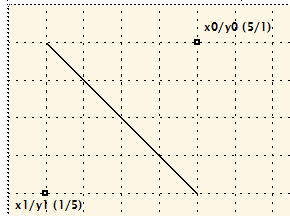
With this log:
A xo/y0 = 9288565 1857713 x1/y1 = 1857713 9288565
B xo/y0 = 1857713 1857713 x1/y1 = 9288565 9288565
Copy link to clipboard
Copied
Hi Klaus,
sorry I didn't want to attack you, for me it was the solution when fighting with this stuff in SVG, as I never can get this strange geometric kind of thinking into my brain 🙂
Could you try this.
oLine = oDoc.NewLine(oFrame);
oLine.LocX = x1;
oLine.LocY = y0; // --- The line is clearly in quadrant II
oLine.Width = Math.abs(x1 - x0); // this must not be negative!
oLine.Height = Math.abs(y1 - y0);
oLine.Angle = 90;
I rotate the graphic by 90 degress, and line shows from bottom-left to top-right as I would expect. Not sure about the correct Position of LocX and LocY, but I think this would be an Approach which could work.
I think we discussed this before, that changing Points in the API has no effect.
BTW: in your Code you don't assign points to the line, but that doesn't matter, as it has no effect (due to a bug in ESTK).
Good luck.
markus
Copy link to clipboard
Copied
«BTW: in your Code you don't assign points to the line, but that doesn't matter, as it has no effect (due to a bug in ESTK).»
Markus, this stops my endless search for the source of the problem! It makes clear, that lines 34 to 41 in my initially posted script are for nothing. Only the bounding box (LocX/LocY, Width/Height) is used for the drawing of the line. Therefore only in quadrants I and III correct lines are produced.
This also explains, why PolyLines also draws only the left and lower boundary of the box rather than the given vertices (FRMAKER-5651).
So for quadrants II and IV i will add flipping (vertically or horizontally) of the line. Unfortunately this is only possible with an FCode:
FcodeList = new Array(FCodes.KBD_FLIPUPD);
Fcodes(FcodeList);
But this does nothing ...
Back to square one!
Copy link to clipboard
Copied
Eventually I managed to implement the flipping. Now the function works as expected - thanks to the very important hint from Markus.

With this script
/* CreateLines.jsx ====== UTF-8 ===================================================================
Create ines in various angles
Copyleft 2018 Klaus Daube, Zürich, Switzerland, klaus@daube.ch
History 2018-12-19 final solution with two bypasses
*/ ; // ===========================================================================================
#target framemaker
main ();
function main () {
var j, oDoc, oFrame, x0, x1, y0, y1, len, angle, aLines = [], oPoints = [];
CM = 1857713, pi = Math.PI;
oDoc = app.ActiveDoc;
oFrame = oDoc.FirstSelectedGraphicInDoc;
if (!oFrame.ObjectValid()) {
Alert("Select an anchored frame and try again.", Constants.FF_ALERT_CONTINUE_WARN);
return;
}
for (j= 0; j < 12; j++) { // FM-coordinate systemin cm
len = 3;
angle = pi/6 * j; // 0, 30°, 60, 90°, ... ccw
x0 = 6;
y0 = 4;
x1 = x0 + len * Math.cos(angle);
y1 = y0 + len * Math.sin(angle);
aLines
= CreateLine (oDoc, oFrame, x0, y0, x1, y1); }
CreateGroup (oDoc, oFrame, aLines);
} //--- end main
function CreateLine (oDoc, oFrame, x0, y0, x1, y1) {
// Arguments oDoc current document
// oFrame parent object of the drawing object
// x0/y0 coordinates in FM system of starting point [cm]
// x1/y1 coordinates in FM system of end point [cm]
// Returns Line object (for grouping etc.)
// Attention The object Line has various flaws, which need strange bypasses
var CM = 1857713, FRMAKER5819 = 8192, oLine, width, height, aFCodes = [];
aFCodes[0] = FCodes.KBD_FLIPUD; // there is no flipping function in ESTK or FDK
oLine = oDoc.NewLine(oFrame);
width = x1 - x0;
height = y1 - y0;
oLine.Width = Math.abs(width)* CM;
oLine.Height = Math.abs(height)* CM;
if (Math.abs(width)* CM < FRMAKER5819) { // bypasses for FRMAKER-5819
oLine.Width = FRMAKER5819};
if (Math.abs(height)* CM < FRMAKER5819) {
oLine.Height = FRMAKER5819};
if (x0 < x1 & y0 <= y1) { // quadrant I
oLine.LocX = x0 * CM; oLine.LocY = y0 * CM;
}
if (x0 >= x1 & y0 < y1) { // quadrant II
oLine.LocX = x1 * CM; oLine.LocY = y0 * CM;
oLine.GraphicIsSelected = 1; // bypass for FRMAKER-5844
Fcodes(aFCodes);
oLine.GraphicIsSelected = 0;
}
if (x0 > x1 & y0 >= y1) { // quadrant III
oLine.LocX = x1 * CM; oLine.LocY = y1 * CM;
}
if (x0 <= x1 & y0 > y1) { // quadrant IV
oLine.LocX = x0 * CM; oLine.LocY = y1 * CM;
oLine.GraphicIsSelected = 1; // bypass for FRMAKER-5844
Fcodes(aFCodes);
oLine.GraphicIsSelected = 0;
}
oLine.BorderWidth = 0.05*CM; // Stroke-width
oLine.Color = oDoc.GetNamedColor("Magenta");
return oLine;
} //--- end CreateLine
function CreateGroup (oDoc, oFrame, aObjects) {
// Arguments oDoc current document
// oFrame parent object of the items and the group
// aObjects array of objects to be grouped
// Returns Name of group object
var j, nObjects, oGroup, oGraphic
nObjects = aObjects.length;
oGroup = oDoc.NewGraphicObject(Constants.FO_Group, oFrame);
for (j = 0; j < nObjects; j++) {
oGraphic = aObjects
; oGraphic.GroupParent = oGroup;
}
} //--- end CreateGroup
Copy link to clipboard
Copied
Klaus,
could you pls explain, why you are using FCodes and not Angle-property?
Markus
Copy link to clipboard
Copied
Hi Markus,
Rotation by 90° provides the expected result only if the bounding box is a square. As soon as you have different angle (say, x0/y0 is 4/0 and x1/y1 is 1/4 (FM coordinates), then you can correct the situation (exchange x0|x1 on both ends of the line) only by flipping, not by rotation. Just try this in the UI.
Rotation would require to find out the required angle - and currently I'm simply exhausted from this buggy thing - will try next year.
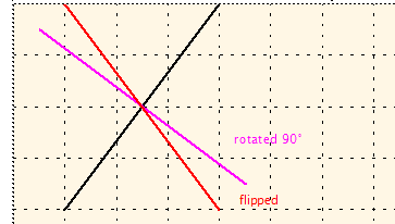
Klaus
Copy link to clipboard
Copied
Well, friends,
to get this routine out of my head I had to change DrawLine according to the recommendation of Markus - replacing the flipping by rotation:
var alpha, RAD2DEG = 57.2957795130823, DEGREE = 65536;
...
alpha = Math.atan2(width, height);
oLine.Angle = (180 - 2*alpha*RAD2DEG) * DEGREE; // bypass FRMAKER-5844
Seasons greetings
Klaus

 AdChoices