 Adobe Community
- Home
- Illustrator
- Discussions
- Re: How do I wrap line segments around circle?
- Re: How do I wrap line segments around circle?
How do I wrap line segments around circle?

Copy link to clipboard
Copied
I'm trying to make a template for an automotive HVAC panel. I've been able to make my circle for knobs just fine and insert icons around those circles at the correct positions. What I can't figure out is how to make line segments of increasing lengths that wrap around the circles like those in the picture below.


Explore related tutorials & articles
 9
Replies
9
9
Replies
9

Copy link to clipboard
Copied
There's a few possible ways to create that effect.
You could create thin rectangles to cut through the circle shape using Pathfinder operations, Center align rectangles across the circle, rotate them to desired positions then cut through the circle shape. It's a slower, manual process but easy to control the results.
Another approach: create a blend using small rectangular dashes and apply it to a circular path. Create the initial blend (and specify the steps needed in the blend). Then select the resulting blend and the target path. Then go to Object>Blend>Replace Spline. This approach is fast if you need even spacing for the blended objects.
An Art Brush applied to a target path is another possibility. I would create an open circle as the target path. Then I would make note of its path length in the Document Info tab (click on the Objects option in the flyout menu). I would create a new flat rectangle shape in the same length as the target path and make all the line cuts through it. That finished compound shape would be dragged into the Brushes pallette and turned into an Art Brush. Select the target path and apply the desired Art Brush to it.

Copy link to clipboard
Copied
I would go for the art brush method. Easiest to control and also to edit if it doesn't match what you want (which can get really important).
-> Great tip about the Document info panel!
Copy link to clipboard
Copied
Getting the path length of the target path is very handy for creating an Art Brush that will deliver more predictable results. I put together the attached sample graphic using two Art Brushes. One features a circular line sweep with dashes cut through it. The other Art Brush is made from lettering creating using an OTF Variable font with weight and width axes. The dummy line after the word "zero" is there to counteract any letter overshoots past the baseline or cap line that might throw off the center. I fine tuned the type object's weight and width axes so it would match the target path exactly:


Copy link to clipboard
Copied
defaultg,
Depending on the actual properties of your HVAC panel, any of the approaches suggested by Bobby can be the most efficient one.
If the properties of your HVAC resemble those shown in the photo, I would suggest an elaboration on the first one, basically simply drawing the HVAC panel in steps, taking advantage of the symmetry round the shortest white top line (and the centre of the empty bottom part), and at the same time incorporating the complications, including the overlapping of the opposite line growths outwards from the centre, the fact that the identical line growth for red and blue is quite different to the dual one for white, and the separation of the thicker end lines that would otherwise form parts of the last (red/blue) lines.
The following images show possible steps in creating such a HVAC panel, which can be made (with reduced opacity) on top of a locked template or sketch, in any case starting out with a (circular) filled background (and a nostroke/nofill counterpart) and the outer boundary of the HVAC as a stroked circle, ever working with stroked paths until you have established the right widths and angles before switching to filled paths, mirroring the dividing paths while drawing them, creating the end lines and the general lines separately, and finally recolouring; if your HVAC panel has no thicker end lines, steps 6) - 9) and 13) can be skipped.
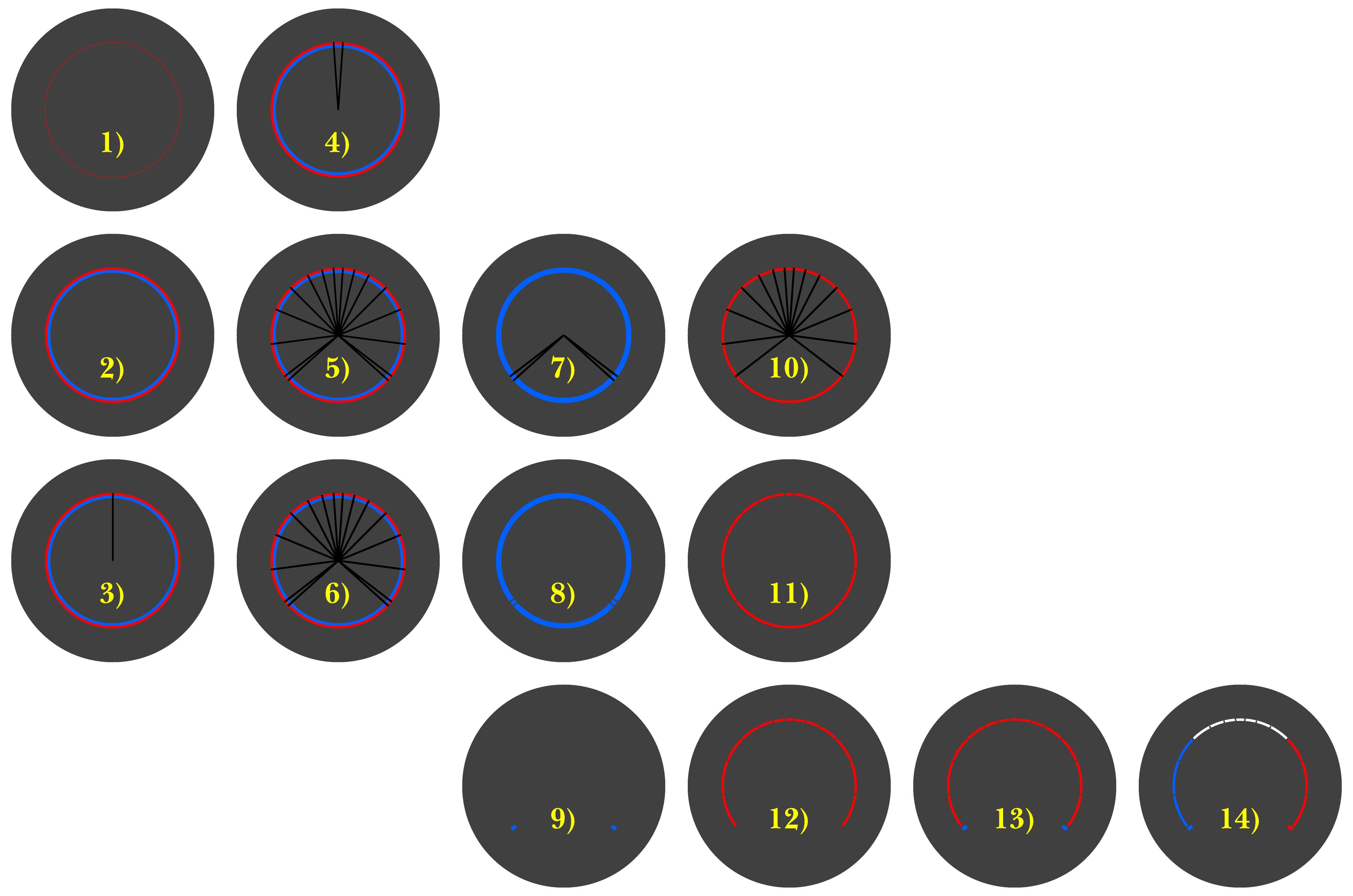
Click/RightClick to get closer, Click again to get closer still
Copy link to clipboard
Copied
Thank you so much for the replies! I've spent hours trying to figure out how to do this but I'm just stumped. These techniques are just way over my head. If anyone is interested in helping me out I'd be happy to pay for some time.
Copy link to clipboard
Copied
defaultg,
How close is the image with step 14) to the desired look?
You can describe it, maybe including answers to these questions:
- Should it have thicker end lines like the HVAC in the photo and step 14), or
- Should it just have the same line thickness, and
- Should it be symmetrical and with three colours as in the photo and step 14) or how?
Or you can make a rough sketch, maybe just drawn on paper.
If relevant, you can have instructions for the steps.
Copy link to clipboard
Copied
Please check out this video: https://youtu.be/WMpso__eP6g
Copy link to clipboard
Copied
Wow! That video is fantastic. Thank you so much! I think that should get me there.
Copy link to clipboard
Copied
Glad I could help you.

 AdChoices