 Adobe Community
- Home
- Illustrator
- Discussions
- 3d rotate / isomatric doesn' work properly
- 3d rotate / isomatric doesn' work properly

Copy link to clipboard
Copied
Hello,
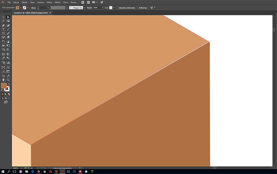
I've noticed something working with Illustrator and Effects->3d->Rotate. I create 3 perfect squares. I use "isometric left" on left one, "isometric top" on middle one and "isometric right" on right one. Middle and left match perfectly but right doesn't. Anybody know why is that?


 1 Correct answer

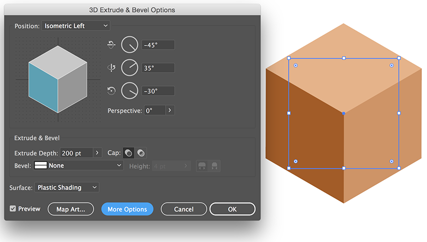
Note that when you select one of the "isometric" presets in 3D Effect, the middle of the three Rotation values is 35°. That is the integer rounding of the isometric tilt angle, which is actually 35°16" (thirty-five degrees, 16 minutes).
(Strictly speaking, 35°16" is also a rounded approximation, albeit a far more accurate one than 35°. The actual value of the isometric angle is the arcsine of the tangent of 30°, which is 35.264389682754654315377000330019 at 30 decimal places. )
In principle, what'
...Explore related tutorials & articles
 9
Replies
9
9
Replies
9
Copy link to clipboard
Copied
I do not know if you have a special reason to construct it this way (and I don't know why the sides don't match perfectly).
But here is another way to get the effect.
Make a square and use 3D Extrude & Bevel.
When you are done you can choose Object >Expand Appearance to get the individual objects.
Copy link to clipboard
Copied
It is correct, but sometimes I would like to align this way, for example 3 sides of complicated structure as building. So I make flat 2 sides of building and roof. Then roof - > isometric top, one wall isometric right and next one isometric left. Can you see the point? Squares where just to show the error.
Copy link to clipboard
Copied
I see.
If you compare coordinates of the top and bottom points of your sides, you will notice that they are not in a straight vertical line.
The same is true for my method, but at least they have the same distortions.
Copy link to clipboard
Copied
Note that when you select one of the "isometric" presets in 3D Effect, the middle of the three Rotation values is 35°. That is the integer rounding of the isometric tilt angle, which is actually 35°16" (thirty-five degrees, 16 minutes).
(Strictly speaking, 35°16" is also a rounded approximation, albeit a far more accurate one than 35°. The actual value of the isometric angle is the arcsine of the tangent of 30°, which is 35.264389682754654315377000330019 at 30 decimal places. )
In principle, what's going on is the same thing as someone drawing isometrically "on the board," but using a regular 35° drafting ellipse template as a "close enough" approximation, instead of using a proper isometric ellipse template.
So enter 35.26° where the preset shows 35° and you'll see that the geometry better approximates the orthographic projection which results from isometric drawing.
JET
Copy link to clipboard
Copied
Thanks. So it's not an error, just approximation matter and best way to avoid it is just draw isometric (or rather dimetric) grid and align to it. Am I right?
Copy link to clipboard
Copied
Thanks. So it's not an error, just approximation matter...
It's a rounding of a value which is similar to an approximation "cheat" which was commonly used in the pre-computer days of iso drawing "on the board," and which was considered rather sub-standard even back then, because dedicated isometric ellipse templates were commonly available.
Back in those days, there was a distinction sometimes made between what was referred to as "isometric drawing" as opposed to "isometric projection." In a nutshell, "isometric drawing" referred to using enlarged ellipse templates (accurate templates labeled isometric) in order to use full-measure (not foreshortened) along the axes. Inversely, "isometric projection" referred to using down-scaled (foreshortened) measure along the axes in order to use ordinary drafting ellipse templates. That practice also was a rather inaccurate approximation; a foreshortening of 75% was commonly used, when the proper scale would actually round to 82%. One of the most common and most egregious error was committed when a beginning illustrator would forget and use ordinary 35° drafting ellipse templates with full measure along axes, resulting in dead-giveaway grossly disproportionate objects.
That kind of "cheat" was arguably forgivable in the days of drafting machines, plastic templates, and Rapidiograph pens. But I see no excuse for it in software.
I've built multiple interactive semi-automated solutions for my own use (Flash based, JavaScript, SVG) which have a stop at the isometric angle between 35 and 36 degrees. I see no reason 3D Effect (since its angle fields do accept values to at least two decimal places) couldn't do likewise. My guess is the assumption was that rounding to 35° is "close enough." But as you've discovered, it often isn't.
...best way to avoid it is just draw isometric (or rather dimetric) grid and align to it. Am I right?
You specified isometric, not dimetric. So I'm not sure why you're mentioning it here. You wouldn't draw a dimetric grid in order to draw in isometric. But, frankly, having done mechanical axonometric drawing since well before personal computers, I've never resorted to grids, and have very seldom seen professional mechanical illustrators use them, and even then only as an underlay when drawing freehand on a pad. I've only used them in software when the grids have some actual functionality. (For examples, see Corel Technical Designer or Serif DrawPlus or to a lesser degree, Serif Affinity.)
The whole point of isometric drawing is to enable the illustrator to efficiently draw "directly into" the mechanically-correct perspective (yes, it's a "perspective" view, just not a converging perspective) without having to resort to things like grids. Grids are fine for trivial things consisting mainly of boxy shapes conveniently aligned parallel to the axes and to each other (like early faux "3D" video games). But in mechanical illustration (parts catalogs, for example), that doesn't get you very far as soon as you encounter object edges which are not so conveniently aligned. That gets you into simple and compound rotations, and a grid would be of little help.
Once an illustrator really understands the principles of axonometric drawing, he doesn't need grids--again, unless they actually add some programmatic advantage.
JET

Copy link to clipboard
Copied
I made some Illustrator Actions to do it, from this video
Don't know if they run into the same problems JET is talking about
Adobe Illustrator Isometric Action Tutorial - YouTube
3 of them here- Left Right and Top
There's Top counter clockwise you can make too '

Copy link to clipboard
Copied
A,
Perhaps the most/completely accurate way, and just using the old inbuilt tools, would be to (with Smart Guides as your friends):
1) Create a hexagon with the Polygon Tool, then deselect and with the Direct Selection Tool ClickDrag over two opposite path segements and delete tehm, then ClickDrag either of the remaining open paths by one of the end Anchor Pont to snap to its counterpart, then Join (Ctrl/Cmd+J, for older versions you may need to join twice, the first time with the Direct Selection Tool at one set, or see below) to have the first face (it matters little which);
2) Rotate a copy by 60 degrees and snap in the same way for the second face;
3) Repeat 2) for the third face;
You may Group and/or rotate by + or - 30 degrees, the latter to have it oriented differently.
Especially for old versions, you may also use the free Join Reasonably script available here, to join in one go:

Copy link to clipboard
Copied
Just cross linking to this thread regarding the relative accuracy (or otherwise) of illustrator's isometric functions as there's a lot of quality, relevant posts there on this subject.

 AdChoices