 Adobe Community
Copy link to clipboard
Copied
Hi forum.
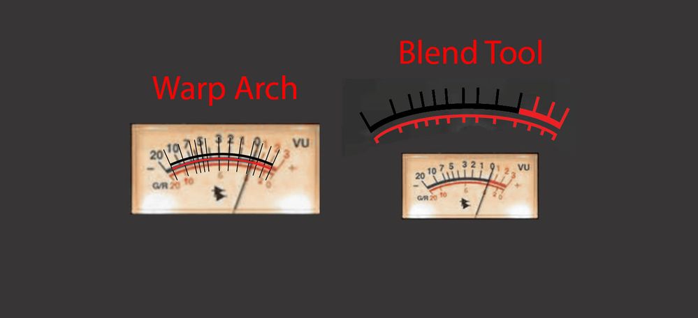
I'm trying to design a UV metre. I tried techniques, one using the Blend tool, and the other with the Warp Arch method. I'm not so satisfied with the way the Lines and curves look. So I'd like to get some design techniques on what's the best way to design this UV metre.
 1 Correct answer
inquestflash,
In order to have a design that works properly, like the original, you have to get much closer to hand drawing, but it is quite manageable.
One way is as follows, Smart Guides being your friends (saying when you are within snapping distance), as is Undo (Ctrl/Cmd+Z), and as is the use of a Stroke in a contrasting colour such as yellow, small enough to ensure that it follows the middle of the curved/straight original parts, remember to keep locked/hidden copies of the parts underway
Explore related tutorials & articles
Copy link to clipboard
Copied
I think you can use Polar Grid Tool wih custom option. Unfortunately it not have Preview mode so you need to change parameters and draw it again. After creating you edit it manualy.
or you can use Transform from Effects. After creating effect you have to Expand Appearance from Object Menu for eoving object separately .
Copy link to clipboard
Copied
inquestflash,
In order to have a design that works properly, like the original, you have to get much closer to hand drawing, but it is quite manageable.
One way is as follows, Smart Guides being your friends (saying when you are within snapping distance), as is Undo (Ctrl/Cmd+Z), and as is the use of a Stroke in a contrasting colour such as yellow, small enough to ensure that it follows the middle of the curved/straight original parts, remember to keep locked/hidden copies of the parts underway (so you have them to fall back on):
0) Place the original on a Template Layer at the largest possible size that can be easily scaled to the final size, and start on a new Layer above it, and work at a zoom level that allows precise fitting;
1) With the Line Segment Tool ClickDrag between the ends of the visible part of the indicator, then in the Transform palette select the top right Reference Point and multiply the W or H value by a sufficient number (maybe 1.5) and press Ctrl/Cmd+Enter to extend past its centre of rotation;
2) With the Ellipse Tool create an ellipse that fits the upper scale nicely and has its centre on the line from 1);
3) Object>Path>Offset Path with a negative Offset that gives a fit on the lower scale; you may use Undo for just 3) or for both 2) and 3), depending on the accuracy of the original, to get the best overall fit (if any, I would weight the upper higher in this); copy all the marks and lock the originals;
4) Select the upper scale ellipse and Object>Path>Offset Path with a positive Offset to fit the upper ends of the upper marks, then Object>Path>Offset Path with a negative Offset to fit the lower ends of the lower marks
5) For the upper scale, with the Line Segment Tool ClickDrag from the upper end of each mark (at the upper ellipse) to the centre (of rotation/the ellipses), then extend beyond the upper ellipse as in 1) if needed (see below);
5) Repeat 4) only for the lower scale;
Especially at the rightmost end of the scales, the marks will become more precise than the originals which point in quite different directions;
The order/exact way of the following depends on the desired appearance of the ends of the marks and the scales: if the ends of the marks are to follow the upper end ellipse (slanting and sharp) rather than having a simple rounded (or rectangular) end/Cap, you need to end up with outlined fill/nostroke paths, otherwise you can keep them as stroked paths; and the same goes for the scales;
7) Increase the Stroke Weight of all parts to match the originals;
8 ) Cut all parts as desired, either
8a) Cut the upper/lower marks at the intersections with 2)/1) and the upper/lower end ellipse and hide/delete the unneeded parts, and also cut the scales, and extend the upper mark at 0 to reach the bottom of the upper scale; or
8b) Select all the parts and Object>Path>Outline Stroke and use the Pathfinder operations to cut;
9) Set the colour of all parts; cut the upper scale so it switches from black to red just to the right of the upper mark at 0;
10) Add the numbers, letters, and signs.
Copy link to clipboard
Copied
Thanks for this detailed insight!
Kind regards.
Copy link to clipboard
Copied
You are welcome, inquestflash.
And thank you for a pleasant challenge. I hope you will complain if more/better is needed.


