 Adobe Community
- Home
- Lightroom Classic
- Discussions
- Re: SDK: Computing the corners of a crop rectangle
- Re: SDK: Computing the corners of a crop rectangle
SDK: Computing the corners of a crop rectangle
Copy link to clipboard
Copied
[This post has been substantially rewritten to correct some previous errors.]
Over the years, I’ve been asked how LR represents coordinates of crops and brush strokes. Recently, I was asked how to compute the corners of a crop rectangle. It’s time to write it down for everyone.
I've attached a script "crop-corners.lua" that displays the coordinates of the crop rectangle for the current photo. The top of the script explains how to install and run it. I've also attached a 1000-800 pixel image with 100 x 100-pixel grid, to make it easy to observe the results of crop computations:
Here's an overview of the computations in the script:
A photo is stored in a file as an array of pixels (typically but not always in landscape orientation) along with an EXIF Orientation field that specifies how that array of pixels should be rotated in 90-degree increments and mirrored around the vertical axis to produce the intended visual appearance.
For example, if you rotate your camera 90 degrees clockwise to take a portrait, it will store the photo in the raw file as a landscape array of pixels, with the EXIF Orientation set to “Rotate 90 degrees clockwise”.
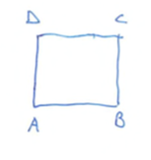
In the SDK, photo:getDevelopSettings().orientation provides the stored orientation as a two-letter code with the letters A, B, C, and D. To interpret the code, label the corners of the stored array of pixels as:
The orientation codes for the rotations of 0, 90, 180, and 270 degrees clockwise are:
The code is the two letters along the bottom edge. If the photo is mirrored along the vertical axis, then the letters will be reversed: BA, AD, DC, CB.
LR represents a crop rectangle with these numeric fields in photo:getDevelopSettings(): CropLeft, CropTop, CropRight, CropBottom, CropAngle. The upper-left corner of the rectangle is (CropLeft, CropTop) and the lower-right corner is (CropRight, CropBottom). These coordinates are in the develop coordinate system, in which x- and y-coordinates are in [0..1], with (0, 0) being the upper-left corner. They represent coordinates with respect to the array of pixels stored in the photo before any orientation is applied.
CropAngle specifies the amount the crop rectangle has been rotated around its center (positive = clockwise, negative = counterclockwise). Here I refer to code angle a = -CropAngle (positive = counterclockwise), to match the conventions of high-school math).
Define the develop pixel coordinate system as pixel coordinates relative to the array of pixels before orientation has been applied. The x-coordinates are in [0..w] and the y-coordinates in [0..h], with the origin (0, 0) in the lower-left corner, where w and h are the width the height of the array of pixels. (Most graphics libraries use the upper-left corner as the origin, but I use the lower-left so that high-school math recipes I find online don’t need translation.)
Here are the steps to obtain the pixel coordinates of the crop rectangle's corners. Refer to this diagram:
1. Get the crop parameters from the photo:
d = photo:getDevelopSettings ()
a = -d.CropAngle
2. Get the dimensions of the photo in develop pixel coordinates:
dim = photo:getRawMetadata ("dimensions")
dimd = {x = dim.width, y = dim.height}
if mod (orientationTranslation [d.orientation].n90CW, 2) == 1 then
    dimd.x, dimd.y = dimd.y, dimd.x
    end
3. Compute the upper-left and lower-right corners of the crop rectangle, converting from develop coordinates to develop pixel coordinates:
uld = {x = d.CropLeft * dimd.x, y = (1 - d.CropTop) * dimd.y}
lrd = {x = d.CropRight * dimd.x, y = (1 - d.CropBottom) * dimd.y}
4. Get the center of the crop rectangle, halfway between the upper-left and lower-right corners.
cd = {x = (uld.x + lrd.x) / 2, y = (uld.y + lrd.y) / 2}
5. Next, level the rectangle and compute the “unrotated” corners uul and ulr by rotating ul and lr around c by -a degrees:
uuld = pointRotate (uld, cd, -a)
ulrd = pointRotate (lrd, cd, -a)
6. Compute the other two unrotated lower-left and upper-right corners:
ulld = {x = uuld.x, y = ulrd.y}
uurd = {x = ulrd.x, y = uuld.y}
5. Rotate the unrotated lower-left and upper-right corners around c by a degrees, yielding all four corners of the rotated rectangle:
lld = pointRotate (ulld, cd, a)
urd = pointRotate (uurd, cd, a)
6. Translate the corners from develop pixel coordinates to visual pixel coordinates as specified by the orientation:
ulv, urv, lrv, llv = rectTranslate (uld, urd, lrd, lld, dimd, d.orientation)
See the attached script for the implementation of pointRotate and rectTranslate.
Update: The new version of the script also shows how to translate corners in visual pixel coordinates back to the develop coordinate system used internally by LR.
Copy link to clipboard
Copied
Thank you for sharing this information with the developers community.
Very, very helpfull!


