Copy link to clipboard
Copied
Hey guys,
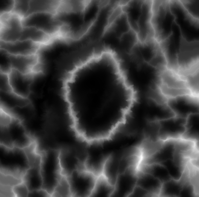
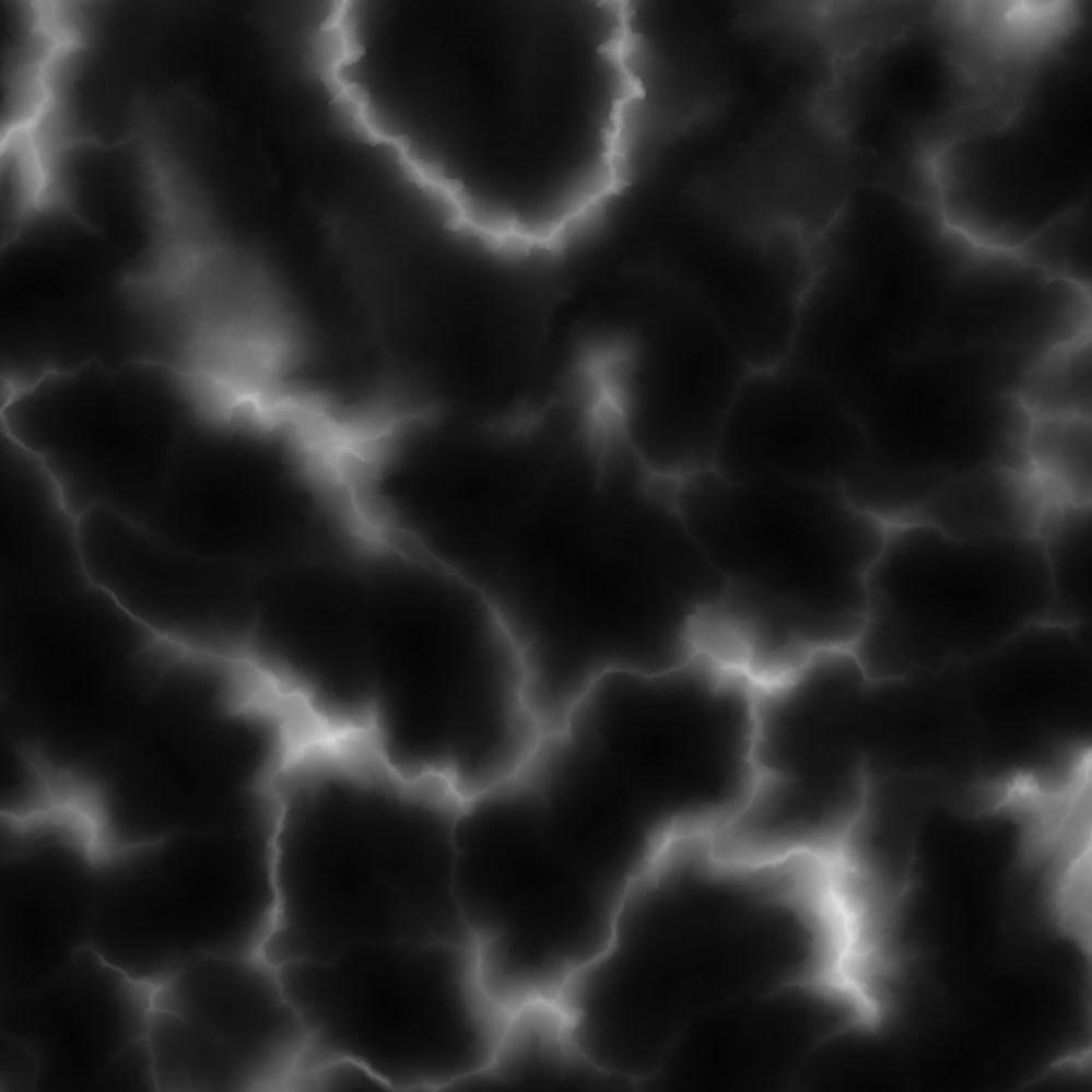
Is there a way in designer to generate a mask by slope angles of the terrain height map? Here's the height map I have:
Can I generate a mask in areas that have angles let's say from 0 to 20degrees? Just for a reference here's how it should look like:
Thank you very much!
 2 Correct answers
Hi
After some thought, I came up with this much nicer solution based on the pixel processor and a bit of math to calculate the surface normal at any point and then the angle between that and a vertical normal. It needs three inputs to generate a mask.
1. The ratio of height to pixel width of the map which is needed in order to calculate an angle. So if your height map is x metres, or miles, wide, what does value 1 (full white) represent as a ratio of that height. Example : If the map represents
Hi
The floor of your map example map measures 1000 x 1000 metres in each direction . But what does the height range (0 minimum to 1 maximum) represent? If it represents 0 to 1 metre then you would enter height/length = 1/1000 = 0.001 and all the angles are going to be very shallow, if it represents 0 to 1000 metres then you would enter height / length = 1000/1000 = 1 and some of the angles are going to be very steep. If you use want accurate min/max angles in the mask then what that height scal
...Copy link to clipboard
Copied
One way:
You could use a pixel processor to sample the 8 neighbouring pixels around each heightmap pixel and calculate the difference. In the example below I used the largest difference out of those 8 but you could refine that. The function in the pixel processor below returns 1 for no difference i.e. flat and 0 for maximum difference i.e. vertical. Then use a histogram scan to adjust what you want included in the mask.
Note : Your sample heightmap was only 8 bit - I would recommend at least 16F, to get decent results as the height differences between neighbouring pixels are small.
Dave
Copy link to clipboard
Copied
Thanks for the reply Dave! This looks very promising! I'm not too familiar with pixel processor workflows though. Could you please send me the actual node in SD file so I can just use it in my graph?
Copy link to clipboard
Copied
Actually I tried to replicate the graph in the Pixel Processor using your screengrab as a refeence and it's possible that I missedlinked some of them as sometimes it was hard to guess where each link ended up. So I got the desired result but for some reason Histogram Scan node's position parameter is too sensitive - so in order to play with this 'slope' value I really need to enter high-precision values manually such as 0.001 to 0.1 instead of having normal range of 0 to 1. Am I doing something wrong or this is expected?
And related question is there a way to remap value ranges from 0-0.1 to 0-100 for example?
Thanks in advance!
Copy link to clipboard
Copied
Also, I experience some weird artifacts even on 16bit height map file:
Is it caused by Pixel Processor calculations or is the problem in the source PNG?
Providing 16bit png for you to check! Thanks in advance!
Copy link to clipboard
Copied
Hi
I've attached an SBS and in it have two alternative pixel processor methods. One is using the method described above but with a scale input added. The second uses a normal map. The outputs are similar but may help you if you are getting artifacts with either method.
For those artifacts - a minute amount of BlurHQ on the output of the pixel processor will help.
Dave
Copy link to clipboard
Copied
Hey Dave thanks a lot it already works great but there's just one thing I;m puzzled about. Currently with both options you showed - even if I crank up Position param to its max -1, there are still some black values left:
Shouldn't it all be flat white when position is 1 (covering all slopes)?
Copy link to clipboard
Copied
Ah - that was my fault. The scale input which I introduced to avoid small values was causing some outputs to be negative numbers when subtracted from 1. I have added an aditional node to the end of the pixel processor function to avoid that problem. You will still need to play with the scaling and histogram scan for each map. I've attached the revision below.
I have some thoughts on a better way to implement this slope from height and will take another look when I get some time later this week.
Dave
Copy link to clipboard
Copied
That would be really great Dave thank you very much! Cos this solution you outlined helps indeed, but still quite hard to achieve precise slope values unfortunately, being quite risky to rely on for 100%. Currently I still have to render slope mask from Houdini to compare both results to be sure slope mask-from-heightmap is similar to mask-from-3DSurface which solves it but still is very inconvenient.
So ideally it would be fantastic to have a Pixel processor setup that for example if I'd want a 0-45° angle slope mask - I'd just set the Position slider of Histogram Scan node to 0.5 and as a result it would fill in all areas from flat 0° to 45° slopes with pure white.
Once again thanks a lot for your time and effort!
P.S. By the way is there some course/tuts you could recommend to learn this pixel processor magic you did? Thanks!
Copy link to clipboard
Copied
Hi
The pixel processor allows you to create a function that operates on each individual pixel in the image input. It allows you to create some effects that cannot be done by the existing nodes alone. Many existing nodes provided with Substance Designer make use of the pixel processor.
It does have some limitations, for example each pixel is processed in isolation - you cannot store a result from pixel one to be used when processing pixel 2 etc. But it is worth experimenting with.
There is documentation here:
https://substance3d.adobe.com/documentation/sddoc/pixel-processor-172825311.html
and some tutorials here:
https://substance3d.adobe.com/tutorials/courses/using-the-pixel-processor/youtube-rL55dq3LfB8
Dave
Copy link to clipboard
Copied
Thanks a lot!
Copy link to clipboard
Copied
Hi
After some thought, I came up with this much nicer solution based on the pixel processor and a bit of math to calculate the surface normal at any point and then the angle between that and a vertical normal. It needs three inputs to generate a mask.
1. The ratio of height to pixel width of the map which is needed in order to calculate an angle. So if your height map is x metres, or miles, wide, what does value 1 (full white) represent as a ratio of that height. Example : If the map represents 1024 metres wide and the difference between full black and full white is 512 metres height then set that ratio to 0.5. This is needed in order to calculate an angle.
2. A minimum angle for the mask
3. A maximum angle for the mask
The pixel processor function:
I hope it helps
Dave
Copy link to clipboard
Copied
Thanks for getting back to me with this solution!
But I have a couple questions still.. (sorry my math skills are terrible)
I'm a bit puzzled what this phrase means:
If the map represents 1024 metres wide and the difference between full black and full white is 512 metres height then set that ratio to 0.5
The heightmap represents 1000x1000 meters and was rendered as a 8192x8192px grayscale 16bit single channel png file (the one I provided a few posts earlier but downsaled to 2048x2048 so that I can attach it here). So I'm not sure which values should I input into height ratio input - would 0.5 be fine for that?
Another question so if I want to have a 0 - 20° mask - should I need to set Min Angle to 0 and Max Angle to 20?
Thanks!
Copy link to clipboard
Copied
Hi
The floor of your map example map measures 1000 x 1000 metres in each direction . But what does the height range (0 minimum to 1 maximum) represent? If it represents 0 to 1 metre then you would enter height/length = 1/1000 = 0.001 and all the angles are going to be very shallow, if it represents 0 to 1000 metres then you would enter height / length = 1000/1000 = 1 and some of the angles are going to be very steep. If you use want accurate min/max angles in the mask then what that height scale represents is an essential input.
'The heightmap represents 1000x1000 meters and was rendered as a 8192x8192px grayscale 16bit single channel png file (the one I provided a few posts earlier but downsaled to 2048x2048 so that I can attach it here). So I'm not sure which values should I input into height ratio input - would 0.5 be fine for that?'
In your example, by entering 0.5 you are saying that the height range represented by 0 to 1 values in the map is 0 to 0.5 x 1000 = 500 metres
'Another question so if I want to have a 0 - 20° mask - should I need to set Min Angle to 0 and Max Angle to 20?'
Yes but, as stated above, those values can only be accurate if you have entered the height proportion value accurately.
Dave
Copy link to clipboard
Copied
Oh I got it now! Yes sure, the actual physical height of my terrain is 85 meters which makes height/length ratio to be 85/1000 = 0.085! Now I got perfect slope masks that are easy to tweak and which are easy to apply to other heighmaps of different height and sizes! Thank you so much once again!
Copy link to clipboard
Copied
You're welcome - it was an interesting challenge to take on.
Dave
Copy link to clipboard
Copied
Hi Dave, sorry for bothering I try to import your node into updated Substance Designer and for some reason it's being imported with some warnings and no node for connecting height map. Do you have any idea why is it happening? Thanks!
Copy link to clipboard
Copied
The graph was made as a demo just to show how you could do it.
To import the graph as a node for use in another graph, you would need to replace the Bitmap node with an input node and add an output node after the Blur. That way when used elswhere it would have an image input and output connection.


