 Adobe Community

Copy link to clipboard
Copied
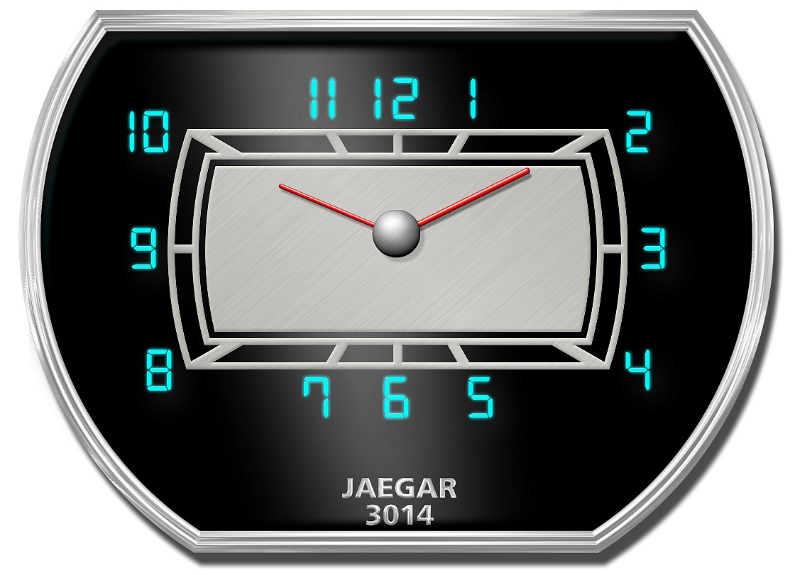
I've got a new Challenge for you guys, hoping you can help me out with this dial. Also, as always I will need very clear instructions as I am by no means a master at Illustrator, not sure I will ever move from the "beginner" class. But anyways, here it is and the numbers are not an issue, but everything else needs to be recreated as close to the original as possible but no need for "exact" as this dial was probably hand drawn back then as most are.
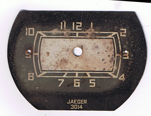
Only the clock face is needed, not the surrounding black area and the tiny holes on each side as well as the larger hole in the middle are not an issue, those are registration marks.
thanks guys!!!


 1 Correct answer

Jber,
Using the original dial as a locked template and having Stroke>Cap and Join set to Round, you may (Smart Guides are your friends):
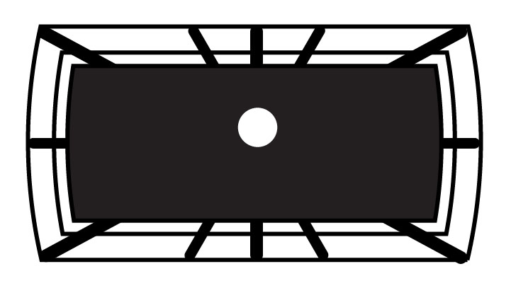
1) Create the rays as follows, every time adjusting the Stroke Weight to fit the original:
1a) Drag horizontally with the Line Tool to create a horizontal line longer than the dial, then Object>Path>Add Anchor Points;
1b) Rotate copies by 30 degrees until you have all the rays;
1c) Centre the rays over the centre of the original;
2) Create the outermost ring shape as
...Explore related tutorials & articles
 17
Replies
17
17
Replies
17
Copy link to clipboard
Copied
Jber,
Using the original dial as a locked template and having Stroke>Cap and Join set to Round, you may (Smart Guides are your friends):
1) Create the rays as follows, every time adjusting the Stroke Weight to fit the original:
1a) Drag horizontally with the Line Tool to create a horizontal line longer than the dial, then Object>Path>Add Anchor Points;
1b) Rotate copies by 30 degrees until you have all the rays;
1c) Centre the rays over the centre of the original;
2) Create the outermost ring shape as follows:
2a) First create a rectangle with the right height (fitting the horizontal segments) and as long as the horizontal ray, then Object>Path>Add Anchor Points once;
2b) Then create a line between the middle Anchor Points of the vertical segments in the sides (you can do that with the Line Tool, dragging from one to the other, Smart Guides say anchor);
2c) Then create a circle with the centre at the middle of the leftmost bend (at 9) and fitting the rightmost bend (from 2 over 3 to 4), it should fit reasonably well, keeping the centre on top of the line created in 2b) (Smart Guides say path), you may adjust size and move the centre horizontally if needed to fit;
2d) Then copy the circle from 1c) and move its centre to the centre of the rays Smart Guides say anchor) and then Object>Transform>Move and press Enter (this will repeat the move to fit the other bend);
2e) Then select both circles and the rectangle and Pathfinder>Divide and Object>Ungroup and delete all the redundant parts;
This should give you the finished outer ring;
3) Cut the rays as follows:
3a) Select each ray and click on it with the Scissors Tool where it crosses the outer ring (Smart Guides say anchor or path);
3b) Select the redundant outer parts and delete them;
4) Create the inner ring as follows:
4a) Object>Path>Offset Path with a negative value equalling the distance between the outer ring and the inner ring, first attempt;
4b) Undo and redo until you have it right;
This should give you the finished inner ring;
5) Create the central part as follows:
5a) Object>Path>Offset Path with a negative value equalling the distance between the inner ring and the central part, first attempt;
5b) Undo and redo until you have it right;
5c) Give the central part a fill;
This should give you the finished central part, and thereby the whole dial.
Copy link to clipboard
Copied
Thanks Jacob!
I was able to follow along without much trouble (guess I'm learning a few things after all lol). I did have an issue with the corner rays not quite meeting up with the ring when I cut them off, but I think it's going to be okay. My only other issue was when I got to the part where I needed to use the "offset path" (this is the first time I've used that tool) I ended up with another outer ring that I didn't want, but I was able to enter isolation mode and remove the unwanted ring, from there I was able to finish without any issues. Here is what I got:
Now, if I wanted to have the original base layer (see original image) with the clock face on top, that layer appears to be nothing more than a filled circle with the top and bottom sections cut off. It's doubtful I will need to recreate it, but I thought I might be nice to know how anyway. I drew a circle, filled, added ancho points, then drew a horizontal line at top and used the scissor tool and cut off the unwanted top part of the circle, I then did the same for the bottom. This did not work out so well, as I ended up with wierd filled areas. Would the shape builder tool have been a better choice for that part?
Regardless, thank you very much, I learned a new tool and I'm really happy with the outcome.

Copy link to clipboard
Copied
Here's another technique
Copy link to clipboard
Copied
Larry,
As I see the original, the side parts are somewhat less bent than would be the case if they were parts of the same circle, hence the clumsier way of using two circles.
Based on an on screen measurement, I believe each should have its centre just about on the arc of the other, corresponding to twice the radius.
Copy link to clipboard
Copied
Thank you Larry. This will come in handy in some circumstances, but for this dial, it doesn't quite give me that wierd bend on the sides that I need. I appreciate the help though.
Copy link to clipboard
Copied
You are welcome, Jber.
Very nice (see below).
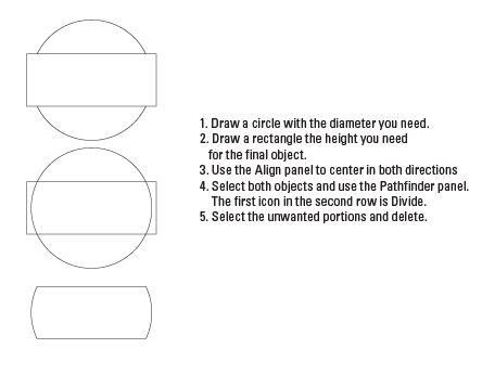
For the base layer, you can (using a different numbering):
i) Create the circle,
ii) Drag horizontally with the Line Tool (holding Shift) where you want each cut;
iii) Select each of the lines and Object>Path>Divide Objects Below;
iv) Delete the top and bottom.
That is very simple and makes no mess/grouping/whatever.
The fitting of the rays and the corners of the outer ring is a bit tricky, with a careful adaption of the latter to the former; that was the reason for my starting with the rays (in the first attempt to decribe it, I started with the rings and adapting the rays, but then I realized that I had to use the exact 30 degrees and so changed the order).
The corner issue may solved it if you make the rings a bit thicker (as I see it they are a bit thinner than the original), and if you make sure that all the parts (rays, rings, and central part) are concentric; you can select all and Align>Horizontal Align Center + Vertical Align Center (if you click one object right after the selection, it will be the key object which stays in place and everything else will move to fit).
Seeing the new version and realizing, I regret two things, sorry:
Some of the Round Caps of the rays are visible, and the rays are visible between the inner ring and the central part.
Both errors can be set right if you (with Scale Strokes & Effects unticked in the Transform palette flyout):
6) Cut the rays at the outer and inner ring as follows:
6a) Select all the rays and in the Transform palette add *1.1 to the W field and press Ctrl/Cmd+Enter to scale them up a bit (this will undo step 3) which was a mistake, sorry;
6b) Object>Path>Outline Stroke to change the stroked open paths into filled closed ones;
Using the (normal) Selection Tool) for the rest:
6c) Select and copy both the outer and the inner ring;
6d) Hide the original outer and inner ring and the central part (click the Eye in the Layers palette);
6e) Click the outer ring and Object>Path>Divide Objects Below, then click the inner ring and Object>Path>Divide Objects Below;
6f) Drag over and delete the outer and inner parts of the rays so that only the parts between the two rings remain;
6g) Show the original outer and inner ring and the central part.
Copy link to clipboard
Copied
Thanks for the fix and clarification Jacob, I'm sure cutting the rays as described above would do the trick in cleaning up those corners and making the basic bottom layer seems easy enough now that you describe it. I appreciate your help as always! I would love to really learn illustrator and I know a lot about it, but when it comes to applying what I've learned is where I get messed up. I mean I know the parts, but I look at something like this dial and I've no idea how to make those "parts" of knowledge into "whole" knowledge. I've tried reading a couple books and watching you tube vids, but hasn't helped much. If you have any suggestions as to methods of learning how to put this stuff together, I would appreciate knowing it.
Thank you again and I'm sure that I will be back with the next challenge!
Copy link to clipboard
Copied
Jber,
Thank you again and I'm sure that I will be back with the next challenge!
It would be a great loss if you were to get too many tips, never to return.
These very pleasant tasks consist of (re)creating combined shapes that are very neat and regular.
I believe the right, or only, way to fulfil them is to take the time to spot the individual basic shapes and their relations, and then choose the tools that can make them and combine them. Obviously, you need to know the tools to be able to recognize when they may be used. And then care is needed.
In this case the rays form one set, which may be made independently and then cut.
The rings and the central part form shapes that are combinations of straight lines and arcs, thus calling for rectangles and circles of sizes to fit.
The special likeness in shape and constant distances between the rings and the central part call for the offset path to create them all from one (and then an important decision is which to choose).
For tasks like these, it may be convenient to centre everything round X = Y = 0, so that you can look at the figures in the Transform palette (using the relevant Reference Points) for guidance and control. Your friends the Smart Guides also work on the Artboard itself, saying page and intersect.
Copy link to clipboard
Copied
Thanks Jacob, I will try to keep those tips in mind when I have my next challenge. I think I undersand what you mean is to look at the individual parts instead of the whole and work from there. That's the best tip of all and I really think it will help.
Thank you for your insight and your invaluable help as always.
Copy link to clipboard
Copied
You are welcome, Jber.
If you wish, next time (hopefully there will be one) an open discussion of how the original can be seen could be worth considering, maybe followed by the different ways it may be recreated (or redesigned if an option and desirable, the key being how the original can be seen and thereby how it could have been different), and if needed how the different possible ways may be realized.
Depending on the task, a redesign may be an option, and in that case there may be different ways/alternatives. With the present dial, an obvious alternative could be more rounded ends using a single circle (instead of the two), as suggested by Larry, combined with scaling (instead of offset path) between the rings and the central part; with that, the 10-4 and 8-2 rays would go through all the corners in exactly the same way (instead of passing by the two innermost sets).
And the discussion might include opinions on the choice between intriguing/quaint/messy and consistent/regular/boring.
Copy link to clipboard
Copied
Jacob Bugge wrote:
You are welcome, Jber.
If you wish, next time (hopefully there will be one) an open discussion of how the original can be seen could be worth considering,.
Hi Jacob;
I'm not sure what you mean by open discussion, is that not how I posted this? Also, I have a dial that is very similar to what we recreated here. It's been so long since I've done these dials, that I tried to follow along with your steps to recreate this one for practice and simply wasn't able to. I sure don't feel like the brightest bulb in the pack at the moment.
Here are your beginning steps and unfortunately, I was lost at the very start.
"i) Create the circle,
ii) Drag horizontally with the Line Tool (holding Shift) where you want each cut;
iii) Select each of the lines and Object>Path>Divide Objects Below;
iv) Delete the top and bottom."
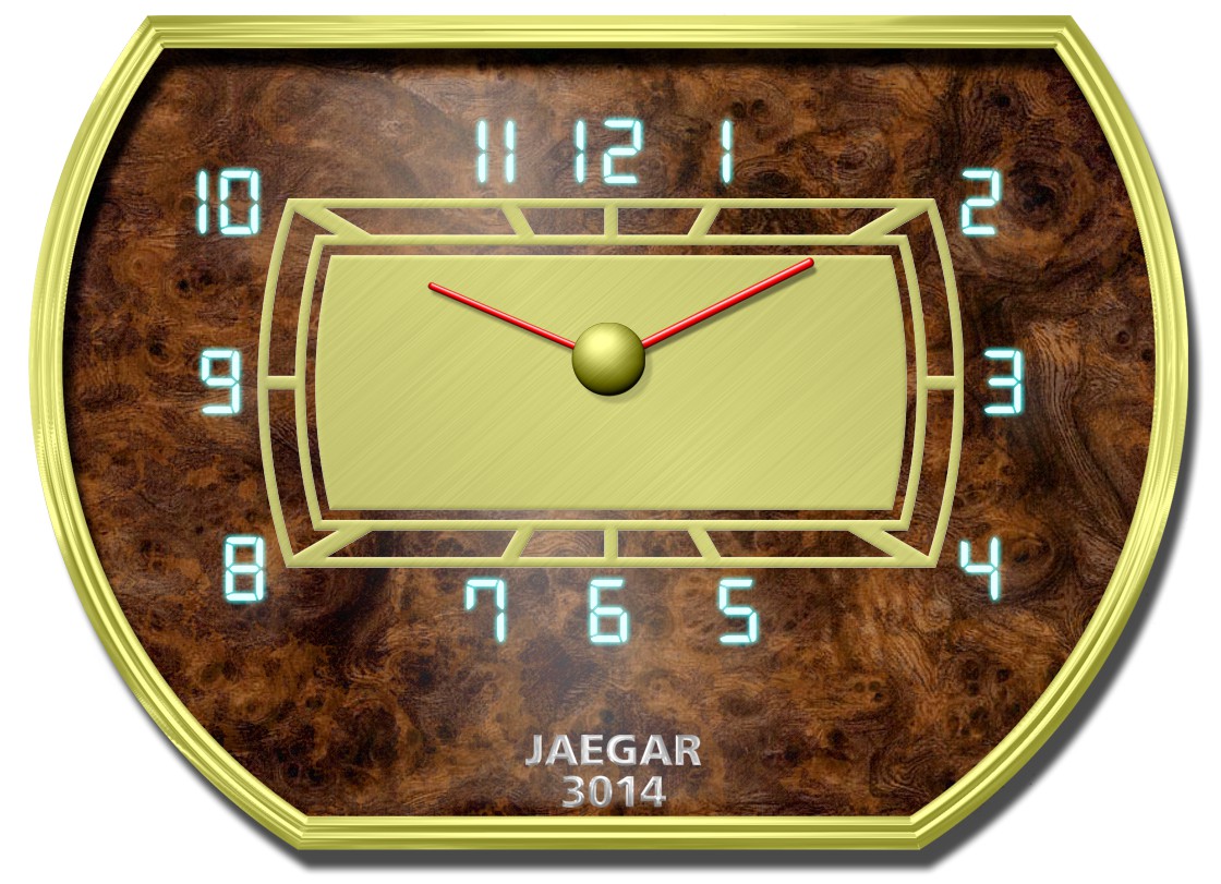
I think it's best if we deal only with the shape itself, let the hash marks go for now. With this dial, the sides are barely bent, and I did try Larry's method also but I was getting too much bend. Here is the dial we are working with now. For this discussion, we are only dealing with the center dial and then only the inner/outer ring/rectangle shape.
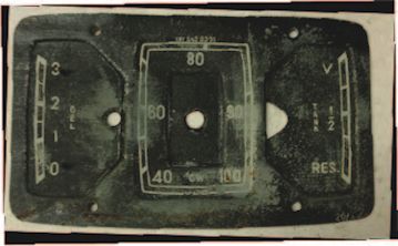
I did increase the size of this image, but the forum must automatically resize images, else I don't know what happend.
Thank you.
Copy link to clipboard
Copied
Jber,
I'm not sure what you mean by open discussion,
I was thinking of a preliminary more woolly step, something like: which kind(s) of shape(s) are we looking at (parts of)?
The full wording was: If you wish, next time (hopefully there will be one) an open discussion of how the original can be seen could be worth considering, maybe followed by the different ways it may be recreated (or redesigned if an option and desirable, the key being how the original can be seen and thereby how it could have been different), and if needed how the different possible ways may be realized.
Looking at the triple set shown in your post #11, a) you may see the outermost curved sides as parts of a high and narrow ellipse, b) the outermost sides of the central part has about the same curvature, and c) you may see the topmost and bottommost sides as parts of a low and long ellipse.
For a) you may lock the image and drag out an ellipse, then edit to fit. After that you may use Object>Path>Offset Path (trying different Offset values) to fit the sides inside the hash marks.
After that you may copy the ellipses a) at top and bottom and move the two parts so they fit b).
After that you may drag out an ellipse and fit it to c), and use offset again.
With this, you would have the basic outer shapes to cut and assemble and fill with the other stuff.
Here is a simple sample of the i) - iv) steps (non symmetrical, just casual):

Copy link to clipboard
Copied
Thanks Jacob, just looking it I think it will help, the illustrations always help so much. I will give it a whirl!

Copy link to clipboard
Copied
My morning challenge completed
Copy link to clipboard
Copied
Great job Mike lol!!! Now if only I can do it.....
Copy link to clipboard
Copied
Glad you like, here was my other wood grain play....
Copy link to clipboard
Copied
LOL show-off!! That's beautiful and I'm completely green with envy 

 AdChoices