 Adobe Community

Copy link to clipboard
Copied
Hello all;
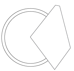
It's been a long time and I'm still plugging away at using Illustrator. I am not a Graphic Artist and use Illustrator to re-create very old instrument panels. I have an old Tach with some fancy work and I have to admit that after all these years, I still don't get the Pen Tool. I know how to use it, I just do so very badly. I don't even know if that's the tool I want in this instance. Here is the dial:
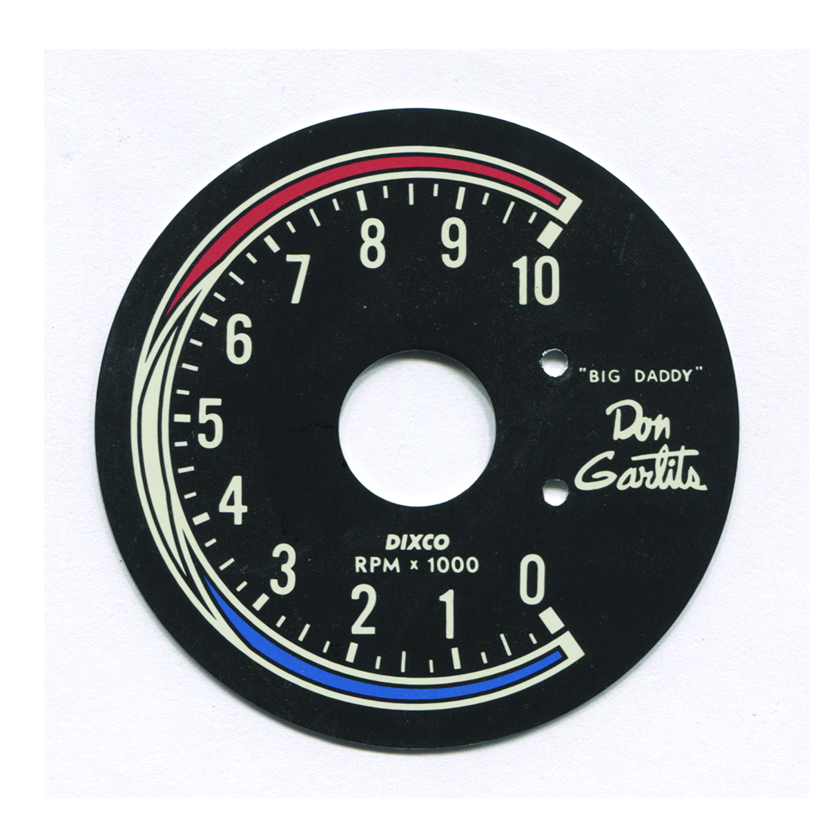
My problem is re-creating the red, white and blue areas. If it were not for the way the ends take off into a point I would not be having a problem. What would be the best way to recreate those 3 color areas? The white area behind it is not an issue.
Thanks for the help, I'm sure that I'm just not seeing something obvious.


 1 Correct answer

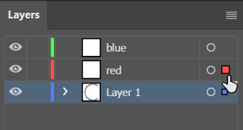
Putting the objects on separate layers is the easy part. Do that last because any groups will need to be ungrouped. Grouped objects all have to be on the same layer.
Once everything is set up, and the new blank layers are created, simply select an object that you want on another layer.

Drag the small dot that represents the selected object on to the layer that it belongs on and release the mouse. The object will be on the right layer and will remain in the exact same position.
Explore related tutorials & articles
 10
Replies
10
10
Replies
10

Copy link to clipboard
Copied
You can build that using circles.
Only those short black lines in my screenshot would need the pen tool. But actually you could start with straight lines and then use the anchor point tool to bend them.
Apply a thick stroke, then outline the stroke.
Then use the shapebuilder tool on this.
Copy link to clipboard
Copied
Here's one way you could do the red, white, and blue unit.
Create a circle. Object > Path > Offset Path so that you have two circles.
Group the two circles.
Create a path on top where you want to cut the circles.
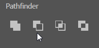
Pathfinder > Minus Front.
Object > Path > Offset Path with a negative number.

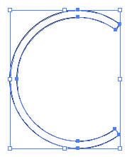
Draw an arc over the two areas where the colors are separated and increase the line weight to the thickness needed.

Select the two arcs and Object > Path > Outline Stroke to get a closed path.
Group the two outlined arcs.
Select the two arcs and just the inner circle.
Pathfinder > Minus Front.

Now you're all set to fill the shapes with color.
Copy link to clipboard
Copied
Thanks to both of you, I very much appreciate the quick response. I will need to try both methods to see which is going to work the best for me as I forgot to mention that I need to have each of the colors on separate layers. Every color will be processed separately making it slightly more difficult. I can't believe that I couldn't see see how this was done, it seems so simple now. Again, thank you. I will get back to you.
Copy link to clipboard
Copied
Putting the objects on separate layers is the easy part. Do that last because any groups will need to be ungrouped. Grouped objects all have to be on the same layer.
Once everything is set up, and the new blank layers are created, simply select an object that you want on another layer.

Drag the small dot that represents the selected object on to the layer that it belongs on and release the mouse. The object will be on the right layer and will remain in the exact same position.

Copy link to clipboard
Copied
Just realized you said "every COLOR" needs to be processed separately. In that case, you need to separate the black stroke from the color fill.
For example, you can select the red object that has a black stroke and choose Object > Expand. They'll be grouped so you need to ungroup them. Now you'll have the black stroke and the red fill as two separate objects.

Copy link to clipboard
Copied
Thank you so much, this worked perfectly. I just couldn't see it.
Copy link to clipboard
Copied
Glad it worked for you.

Copy link to clipboard
Copied
Jber,
A bit late (having been away from the forum), for the fun of it and hopefully for (future) inspiration, here is another approach to the creation of the path(s) enclosing the shapes to colour.
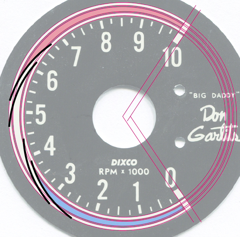
It was based on my immediate impression that everything was made from circles (see the last image for a partly non circular adaptation to the far right), that I was looking at an outer circle and a slightly smaller inner circle offset to the right, that the dividers between the coloured parts were based upon the inner circle, and that everything was fundamentally forming what corresponds to one continuous (compound) path with a white fill and a black stroke (parts of the black stroke being invisible on top of the black background) enclosing the areas to be coloured differently.
As in other pleasant cases it is aimed at allowing the desired degree of accuracy and trueness to the original appearance (without the need for the Pen Tool), with simple steps and a simple structure (and applicable to any version), all based upon the use of circles, compund paths, outlining stroke, and pathfinder operations, applying a temporary contrasting colour (RGB 255/0/128) instead of black, working in points as the unit, starting with the image from the OP placed centred on an A4 Artboard. The rough figures given are just to give a feeling of the sizes/properties (Y values are double such as 400/442pt: first the value if you use CS4 or earlier or have unreversed for CS5 or later, then the reversed value (where 0 is at the top and Y values go down)).
Apologizing for the long and detailed post (in an attempt to make it easy to follow/replicate, there are more images if needed) which makes it look worse than it is, what I created/made/did was, on top of the locked image (it may be worth duplicating the layer and working on a number of times to be able to fall back):
First the basic paths that everything is built upon, all created with 1pt Stroke Weight for accuracy, to follow the middle of white inner parts (see the last remark and image):
1) Create the larger main (partial) circle starting with a rough sizing followed by fitting of size and position (left centre Reference Point in the Transform palette) to have it run in the middle of the white part between the black borders (diameter 810pt, leftmost X value -106pt, centre at 299pt, Y value 400/442pt), revealing that the left ends and also the lower half of the dial are (a bit) off circular shape(s), Ctrl/Cmd+C+B to bring a copy to the back and then hide it for later use;
2) ShiftClickDrag a copy of 1) and adapt its size to create the smaller main (partial) circle (it has to be smaller to fit) in the same way (diameter 735pt, leftmost X value -61pt, centre at 306.5pt, 7.5pt offset to the right from the outer circle, Y value 400/442pt);
3) Move copies of the smaller circle to fit the arcs to divide the areas with the different colours (diameter 735pt, centres at X,Y at 254,351/491pt and 318,338/504pt);
4) ClickDrag with the Line Tool from the centre of 1) to the middle of the white end parts to create cutoff lines to the right, then hide/lock for later use;

Then the building of the structure:
5) Cut the arc circles so only the extended arcs crossing the main circles to the left remain (no other crossing of paths);
6) Select everything and change Stroke Weight to fit the width of the white inner part and half the black outer parts (12pt);
7) Object>Path>Outline stroke to change everything into a set of filled paths;
8) Pathfinder>Divide, then delete the nostroke/nofill paths (you can see them in the Layers palette);
9) Pathfinder>Unite to have one Compound Path;

10) Switch from fill to stroke to give stroked paths corresponding to the black outer parts (5pt Stroke Weight, Miter Limit 20);
11) Show/unlock the cutoff lines 4) and decrease the opacity to 50% (to see through) and increase the Stroke Weight to cover the white part and half the black parts at the ends (27pt);
12) Reset the cutoff lines to 100% opacity and switch from fill to stroke to give stroked paths corresponding to the black outer parts (5pt Stroke Weight, Miter Limit 20);
13) Select everything and Pathfinder>Divide, delete the unwanted outer paths and move the nostroke/nofill paths out of the Group (you can see them in the Layers palette) to prepare for the coloured fills;
14) Select the Group and Pathfinder>Unite to have one stroke/nofill Compound Path along with the three nostroke/nofill paths for the coloured fills;

15) Change the stroke colour to black for the Compound Path
16) Select each of the three nostroke/nofill paths for the coloured fills and apply the desired colour (you can hide/show it while you adjust the colour to match the original colour if relevant), then hide the original image again (the RGB colours shown are 176,8,0 for red, 0,96,255 for blue, and 255,200,255 for the white just used to make it visible as a pale red/blue colour), you can move each to its own layer;

If you wish/need to have the other white parts, and possibly the black parts, as coloured fills you may:
17) Select the Compound Path and give it a white fill, then Object>Path>Outline Stroke, then move the white filled path out of the Group (shown with an even paler red/blue colour with RGB 255,226,255), the Group of black Compound Paths may also go to its own layer;

Last remark and image:
In order to have a better match of the original decisive thinning and drawn out shapes at the ends to the right, you may insert an additional step after 4) where you adapt the original circles by dragging their rightmost Anchor Points to the right with the Direct Selection Tool in connexion with 1) and 2) (shown with the widths increased 810>816 and 735>748 (you may skip the former to have an even more pronounced thinning)); done before step 4) it would move the centre of 1) so the cutoff lines would be skewed.
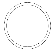
You may compare the obtainable thinning with the appearance above with (completely) circular paths.

Copy link to clipboard
Copied
Jacob, it is so nice to hear from you and to have you weigh in on one of these dial problems of mine. Thank you so much for your very in depth explanation and I will certainly give this a try. I did have an issue with the 2nd method suggested, only because I'm not as deeply educated with Illustrator as you professionals are. Given the fact that I only use Illustrator for technical work, there is so much of the program that I never come into a need for. Anyway, thank you very much I am anxious to see how this works out for me 
Copy link to clipboard
Copied
You are welcome, Jber.
Your dial tasks are always pleasant challenges.

 AdChoices