K.Daube
Community Expert
Community Expert
December 15, 2018
Answered

Drawing lines with ESTK is a nightmare

  • December 15, 2018
  • 2 replies
  • 1363 views

Friends, Romans, countrymen, lend me your ears! I come to bash Adobe [not plain Shakespeare]

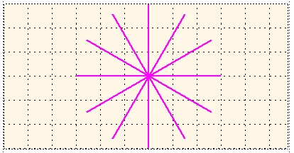
What strange mathematics is necessary to get the lines drawn as they should: all from a centre out at steps of 30°?

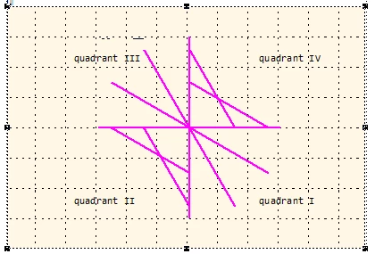
In the FM coordinate system y goes from top to bottom. I have found that the bounding box (aka dimensions) of the object is disconnected from the end points of the line. As You can see from the diagram below, created lines in quadrants II and IV are flipped up/down - after the drawing routine has been left!

How to cope with this strange happening!

// --- Create lines at all 30° angles - FM coordinate system in cm

#target framemaker

main ();

function main () {

var j, oDoc, oFrame, x0, x1, y0, y1, length, angle, oLine, oPoints = [];

    CM = 1857713, pi = Math.PI;

  oDoc = app.ActiveDoc;

  oFrame = oDoc.FirstSelectedGraphicInDoc;

  if (!oFrame.ObjectValid()) {

    Alert("Select an anchored frame and try again.", Constants.FF_ALERT_CONTINUE_WARN);

    return;

  }

for (j= 0; j < 8; j++) {

    length = 3;

    angle = pi/4 * j;                             // 0, 30°, 60° … 330°

    x0 = 6;

    y0 = 4;

    x1 = x0 + length * Math.cos(angle);

    y1 = y0 + length * Math.sin(angle);

    oLine = CreateLine (oDoc, oFrame, x0, y0, x1, y1);

    oPoints = oLine.Points; // after drawing lines in quadrants II and IV are flipped up/down!

    $.writeln ("b xo/y0 = " + oPoints[0].x/CM + "\t" + oPoints[0].y/CM );

    $.writeln ("b x1/y1 = " + oPoints[1].x/CM + "\t" + oPoints[1].y/CM );

  }

} //--- end main

function CreateLine (oDoc, oFrame, x0, y0, x1, y1) {

// x, y are the location of endpoints [cm]; FM-coordinate system!

var j, oLine, oPoints = [], oPoint=[], width, height,

    CM = 1857713, FRMAKER5819 = 8192;

  oPoints.length = 0;

  oLine = oDoc.NewLine(oFrame);

  oPoint0 = new Point(),

  oPoint0.x = x0*CM; oPoint0.y = y0*CM;

  oPoints.push(oPoint0);

  oPoint1 = new Point(),

  oPoint1.x = x1*CM; oPoint1.y = y1*CM;

  oPoints.push(oPoint1);

  width  = x1 - x0;

  height = y1 - y0;

  oLine.Width  = Math.abs(width)* CM;

  oLine.Height = Math.abs(height)* CM;

  if (Math.abs(width)* CM < FRMAKER5819)  {oLine.Width   = FRMAKER5819};

  if (Math.abs(height)* CM < FRMAKER5819) {oLine.Height  = FRMAKER5819};

// --- quadrants in FM coordinate system ---------

  if (x0 <= x1 & y0 <= y1) {$.writeln ("\n------------ quadrant I");

    oLine.LocX = x0 * CM; oLine.LocY = y0 * CM;

  }   

  if (x0 > x1  & y0 <= y1) {$.writeln ("\n------------ quadrant II");

    oLine.LocX = x1 * CM; oLine.LocY = y0 * CM;

  }

  if (x0 > x1  & y0 > y1)  {$.writeln ("\n------------ quadrant III");

    oLine.LocX = x1 * CM; oLine.LocY = y1 * CM;

  }

  if (x0 <= x1 & y0 > y1)  { $.writeln ("\n------------ quadrant IV");

    oLine.LocX = x0 * CM; oLine.LocY = y1 * CM; 

  }

  $.writeln ("a xo/y0 = " + oPoints[0].x/CM + "\t" + oPoints[0].y/CM );

  $.writeln ("a x1/y1 = " + oPoints[1].x/CM + "\t" + oPoints[1].y/CM );

  oLine.BorderWidth = 0.05*CM;                    // Stroke-width

  oLine.Color = oDoc.GetNamedColor("Magenta");

//$.bp(true);

  return oLine;

} //--- end CreateLine

The constant FRMAKER5819 is there to cope with the error described in the respective bug report.

This topic has been closed for replies.
Correct answer K.Daube

«BTW: in your Code you don't assign points to the line, but that doesn't matter, as it has no effect (due to a bug in ESTK).»

Markus, this stops my endless search for the source of the problem! It makes clear, that lines 34 to 41 in my initially posted script are for nothing. Only the bounding box (LocX/LocY, Width/Height) is used for the drawing of the line. Therefore only in quadrants I and III correct lines are produced.

This also explains, why PolyLines also draws only the left and lower boundary of the box rather than the given vertices (FRMAKER-5651).

So for quadrants II and IV i will add flipping (vertically or horizontally) of the line. Unfortunately this is only possible with an FCode:

FcodeList = new Array(FCodes.KBD_FLIPUPD);

Fcodes(FcodeList);

But this does nothing ...

Back to square one!


Eventually I managed to implement the flipping. Now the function works as expected - thanks to the very important hint from Markus.

With this script

/* CreateLines.jsx ====== UTF-8 ===================================================================

              Create ines in various angles

Copyleft      2018 Klaus Daube, Zürich, Switzerland, klaus@daube.ch

History       2018-12-19                          final solution with two bypasses

*/ ; // ===========================================================================================

#target framemaker

main ();

function main () {

var j, oDoc, oFrame, x0, x1, y0, y1, len, angle, aLines = [], oPoints = [];

    CM = 1857713, pi = Math.PI;

  oDoc = app.ActiveDoc;

  oFrame = oDoc.FirstSelectedGraphicInDoc;

  if (!oFrame.ObjectValid()) {

    Alert("Select an anchored frame and try again.", Constants.FF_ALERT_CONTINUE_WARN);

    return;

  }

  for (j= 0; j < 12; j++) {                       // FM-coordinate systemin cm

    len = 3;

    angle = pi/6 * j;                             // 0, 30°, 60, 90°, ... ccw

    x0 = 6;

    y0 = 4;

    x1 = x0 + len * Math.cos(angle);

    y1 = y0 + len * Math.sin(angle);

    aLines = CreateLine (oDoc, oFrame, x0, y0, x1, y1);

  }

  CreateGroup (oDoc, oFrame, aLines);

} //--- end main

function CreateLine (oDoc, oFrame, x0, y0, x1, y1) {

// Arguments  oDoc      current document

//            oFrame    parent object of the drawing object

//            x0/y0     coordinates in FM system of starting point [cm]

//            x1/y1     coordinates in FM system of end point [cm]

// Returns    Line object (for grouping etc.)

// Attention  The object Line has various flaws, which need strange bypasses

var CM = 1857713, FRMAKER5819 = 8192, oLine, width, height, aFCodes = [];

  aFCodes[0] = FCodes.KBD_FLIPUD;                 // there is no flipping function in ESTK or FDK

  oLine = oDoc.NewLine(oFrame);

  width  = x1 - x0;

  height = y1 - y0;

  oLine.Width  = Math.abs(width)* CM;

  oLine.Height = Math.abs(height)* CM;

  if (Math.abs(width)* CM < FRMAKER5819)  {       // bypasses for FRMAKER-5819

    oLine.Width   = FRMAKER5819};

  if (Math.abs(height)* CM < FRMAKER5819) {

    oLine.Height  = FRMAKER5819};

  if (x0 < x1 & y0 <= y1) {                       // quadrant I

    oLine.LocX = x0 * CM; oLine.LocY = y0 * CM;

  }

  if (x0 >= x1  & y0 < y1) {                      // quadrant II

    oLine.LocX = x1 * CM; oLine.LocY = y0 * CM;

    oLine.GraphicIsSelected = 1;                  // bypass for FRMAKER-5844

    Fcodes(aFCodes);

    oLine.GraphicIsSelected = 0;

  }

  if (x0 > x1  & y0 >= y1)  {                     // quadrant III

    oLine.LocX = x1 * CM; oLine.LocY = y1 * CM;

  }

  if (x0 <= x1 & y0 > y1)  {                      // quadrant IV

    oLine.LocX = x0 * CM; oLine.LocY = y1 * CM; 

    oLine.GraphicIsSelected = 1;                  // bypass for FRMAKER-5844

    Fcodes(aFCodes);

    oLine.GraphicIsSelected = 0;

  }

  oLine.BorderWidth = 0.05*CM;                    // Stroke-width

  oLine.Color = oDoc.GetNamedColor("Magenta");

  return oLine;

} //--- end CreateLine

function CreateGroup (oDoc, oFrame, aObjects) {

// Arguments  oDoc      current document

//            oFrame    parent object of the items and the group

//            aObjects  array of objects to be grouped

// Returns    Name of group object

var j, nObjects, oGroup, oGraphic

  nObjects = aObjects.length;

  oGroup = oDoc.NewGraphicObject(Constants.FO_Group, oFrame);

  for (j = 0; j < nObjects; j++) {

    oGraphic = aObjects;

    oGraphic.GroupParent = oGroup;

  }

} //--- end CreateGroup

2 replies

Inspiring
December 17, 2018

Hi Klaus

Drawing lines or other graphic objects is not easy, as it is math and all depends on the coordinate System. faced same issue few days ago with doing same stuff with SVG :-)

In Quadrant II and IV you Need to switch X-coordinate of those two Points.

point2.X = point1.X

point1.X = point2.X

This is strange, but if you draw it on paper by Hand this makes it clearer.

Hope this helps and hope this is all you have to do:-)

Markus

K.Daube
Community Expert
K.DaubeCommunity ExpertAuthor
Community Expert
December 18, 2018

Thanks for Your idea, Markus

I already had the same idea - but this does not help. Inserting the following before line 54 for quadrant II (of course with var declaration of ancillary)

    ancillary = new Point();

    ancillary.x = oLine.Points[0].x;

    oLine.Points[0].x = oLine.Points[1].x;

    oLine.Points[1].x = ancillary.x;

does not have any effect.

Of course I first use paper and pencil when developing a program - especially if there is math and geometry involved. With more than 10 years on the drawing board (I'm a mechanical engineer) I always draw a line from start (x0/y0) to end (x1/y1). And I did so also in many Fortran programs for diagramming.

Most of my scripting problems have the root in very rudimentary documention and unclear specifications (e.g. whether something is an array or an object). A description of graphic functions should IMHO contain drawings - and there should be sample scripts...

The script does something strange (See the log file (values rounded to 1 decimal for better overview):

  • Inside the function (A) the point-coordinates are reported correctly
  • After the drawing (B) for quadrants II and IV the x (or y) coordinates are mirrored.

Hence I thought that changing this already within the function would help - with no positive effect (see above).

I'm really clueless.

Klaus

K.Daube
Community Expert
K.DaubeCommunity ExpertAuthor
Community Expert
December 18, 2018

To demonstrate the problem i have cut the script down to the bare bone: only 1 line to be drawn from up/right to down/left:

#target framemaker

main ();

function main () {

var j, oDoc, oFrame, oLine, oPoints = [], CM = 1857713;

  oDoc = app.ActiveDoc;

  oFrame = oDoc.FirstSelectedGraphicInDoc;

  if (!oFrame.ObjectValid()) {

    Alert("Select an anchored frame and try again.", Constants.FF_ALERT_CONTINUE_WARN);

    return;

  }

    oLine = CreateLine (oDoc, oFrame, 5*CM, 1*CM, 1*CM, 5*CM);  // Single line of shape /

    oPoints = oLine.Points;                                    // => quadrant II

    $.writeln ("B xo/y0 = " + oPoints[0].x + "\t" + oPoints[0].y  + "\t x1/y1 = " + oPoints[1].x + "\t" + oPoints[1].y);

} //--- end main

function CreateLine (oDoc, oFrame, x0, y0, x1, y1) { // FM coordinates in units

var j, oLine, oPoints = [], oPoint0, oPoint1, width, height, ancillary;

  oPoints.length = 0;

  oLine = oDoc.NewLine(oFrame);

  oPoint0 = new Point();

  oPoint0.x = x0; oPoint0.y = y0;

  oPoints.push(oPoint0);

  oPoint1 = new Point();

  oPoint1.x = x1; oPoint1.y = y1;

  oPoints.push(oPoint1);

  oLine.LocX = x1; oLine.LocY = y0; // --- The line is clearly in quadrant II

  oLine.Width  = Math.abs(x1 - x0); // this must not be negative!

  oLine.Height = Math.abs(y1 - y0);

  $.writeln ("A xo/y0 = " + oPoints[0].x + "\t" + oPoints[0].y  + "\t x1/y1 = " + oPoints[1].x + "\t" + oPoints[1].y);

  oLine.BorderWidth = 0.05*CM;                    // Stroke-width

  return oLine;

} //--- end CreateLine

The result is this:

With this log:

A xo/y0 = 9288565    1857713    x1/y1 = 1857713    9288565

B xo/y0 = 1857713    1857713    x1/y1 = 9288565    9288565

Legend
December 17, 2018