


Inspiring
September 8, 2026
Answered

Expanding a drawing in one direction only

  • September 8, 2026
  • 9 replies
  • 61 views

I have a drawing of multiple railway lines that was sketched over from Google Maps. I now need to expand the tracks asymmetrically to I can annotate certain features. If all the tracks were parallel it would be perfectly easy, but they’re not.

The existing drawing is to-scale and good for an overall understanding of the complex. What I now need to do is create something that’s still close to scale horizontally, but expanded vertically to allow the annotations beside each track.

The Illustrator file will be placed into InDesign, and I tried using InDesign to expand the drawing, however everything is skewed in doing so, which I don’t want. Rectangular station platforms become parallelograms, dashed lines likewise, etc.

This is a small part of the drawing as a point of reference.
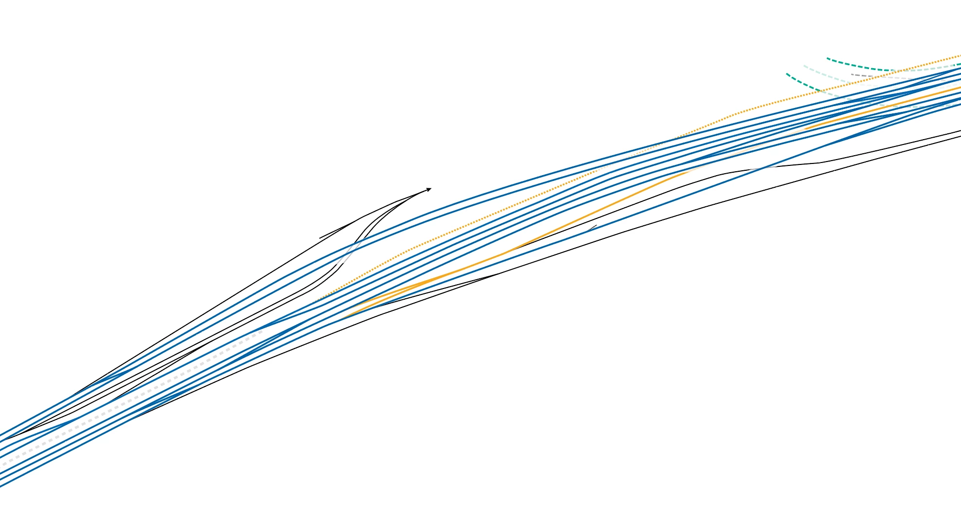
West end of Harold Interlocking, with MID yard and GCB leads.​​​​

The entire drawing is considerably larger and even more complex. I am not a skilled-enough illustrator to re-create this freehand in the format I’d like to have.

Here is a very small example of what I’m trying to accomplish. The three lines on the top are the existing format. The three lines at the bottom along with the symbols are what I want the end result to look like (this is just for display and was done by hand in about 30 seconds). The horizontal components are exactly the same width, but the vertical component is exaggerated to allow the symbols to be added.
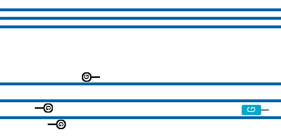
Track expanded vertically to allow for placement of signals and signs

Is this something I could get the AI system to assist with, and if so, how? Or maybe a more conventional way? I’m open to trying anything at this point. Please and thanks.

    Correct answer Bobby Henderson

    One other idea that could work: you could group all of the line work and then scale it non-proportionately in the vertical direction. After doing that you could shear the group of lines to correct the angle. That might work. It might also be helpful to lock down a copy of the original line work on one layer so it can be used as a short of guide to get the altered lines to match the angle.

    9 replies

    Jacob Bugge
    Community Expert
    Community Expert
    September 8, 2026

    Peter,


    “It will probably take at least 6 weeks to do the entire thing (it’s one of the largest rail yards and interlockings in the U.S. and certainly the busiest).”


    If you are moving tracks over 6 weeks you will certainly get in trouble with the operators.


    Sorry, it was stronger than I.


    Presuming each track, including each tracks connecting other tracks, is an object in itself, a simple crude way might be to start with (Smart Guides being your friends):


    1)) Select the first (topmost) regular cyan track along with the attached set consisting of the black track ending with an arrow and the short track attached to the left, then move the whole thing up by the height needed for the additions; lock the topmost track;

    2)) Direct Select (ShiftClick to select both) the upper end anchor points of the black tracks that connects the arrow to the second track;

    3)) Direct Select (ShiftClick to select both) the upper end anchor points of the short cyan tracks that connects the first track to the second (next) one at the left and at the right, then move them up by the same amount as in 1)), this will keep the connexions;

    4)) Select the second regular cyan track, then move it up by the height needed for the additions; lock the second track;

    5)) Direct Select (ShiftClick to select all of them) the set of the lower end anchor points of the short black tracks that connect to each other and to the it to the second track, then move them up by the same amount as in 4)), this will keep the connexions;

    6)) Direct Select (ShiftClick to select all four) the lower end anchor points of the short cyan tracks that connects it to the first track, and the upper end anchor points of the short cyan tracks that connects it to the third track, then move them up by the same amount as in 4)), this will keep the connexions;


    Continue in the same way, adjusting the curvature of the distorted tracks in 2)), 3)), 5)), and 6)), and using similar solutions for other combinations.

    Kurt Gold
    Community Expert
    Community Expert
    September 8, 2026

    Can you share a sample Illustrator file for inspection?

    PeterD-NJAuthor
    Inspiring
    September 8, 2026

    This is the entire Illustrator file.

    Kurt Gold
    Community Expert
    Community Expert
    September 8, 2026


    Thanks for the sample file.

    As per your description I'd suppose the task is about offsetting open paths to increase the spacing between the open paths.

    This is possible by creating custom (Art) brushes and applying them to the existing herd of paths. Unfortunately, caused by non-uniform path directions, it may get a bit complicated, but obviously it can be easier than manually drawing it.

    By the way, Rick Johnson (https://rj-graffix.com) has a very good plugin to offset open paths. You may take a look and see if it could be useful for your task.
     

    Tina_Irvine
    Community Expert
    Community Expert
    September 8, 2026

    Hi ​@PeterD-NJ,

    Try Distribute Spacing in your Align panel.

    You can select a key object (click key icon first) that each line will distance from. Type in a measurement under “Distribute Spacing” and click “Vertical Distribute Space” (bottom left icon)


    Community Expert
    September 8, 2026

    Unless I'm missing some important details it sounds like what you're asking will require multiple steps.

    You could isolate the lines representing the railroad tracks, perhaps turning them into a group and then non-proportionately scale the group so it is taller. But doing that will change the angle of the lines. All of the other elements, such as station platform objects, would have to be re-positioned and maybe even rotated to match the angle of the lines.

    Another idea (but maybe more difficult): repositioning the individual lines vertically to create the desired amount of space between the lines. The problem with this approach is you'll have to do a decent amount of path editing to get all the points where the tracks cross each other or merge into each other depicted accurately.

    PeterD-NJAuthor
    Inspiring
    September 8, 2026

    Yes, that second part is what I’m trying now. It will probably take at least 6 weeks to do the entire thing (it’s one of the largest rail yards and interlockings in the U.S. and certainly the busiest). It’s where all of Amtrak, the Long Island Rail Road and any NJ Transit trains that use Penn Station use or traverse. For the project I’m working on here I’ve eliminated all the yard tracks and I’m concentrating on the main lines (the ones in blue or gold in the drawing). I don’t have the time or patience (or talent) to devote over a month of my life to this, so I’m looking for shortcuts <grin>.

    Repositioning stations takes a few seconds; that’s not an issue. But the way the tracks angle and interconnect (on track becomes two, which becomes three, or whatever), then the whole complex angles to the right, etc, makes things exponentially difficult.