Question
illustartor, comment garder l'arrondi de la forme quand on supprime le tracé
illustartor, comment garder l'arrondi de la forme quand on supprime le tracé
De 1 passer à 3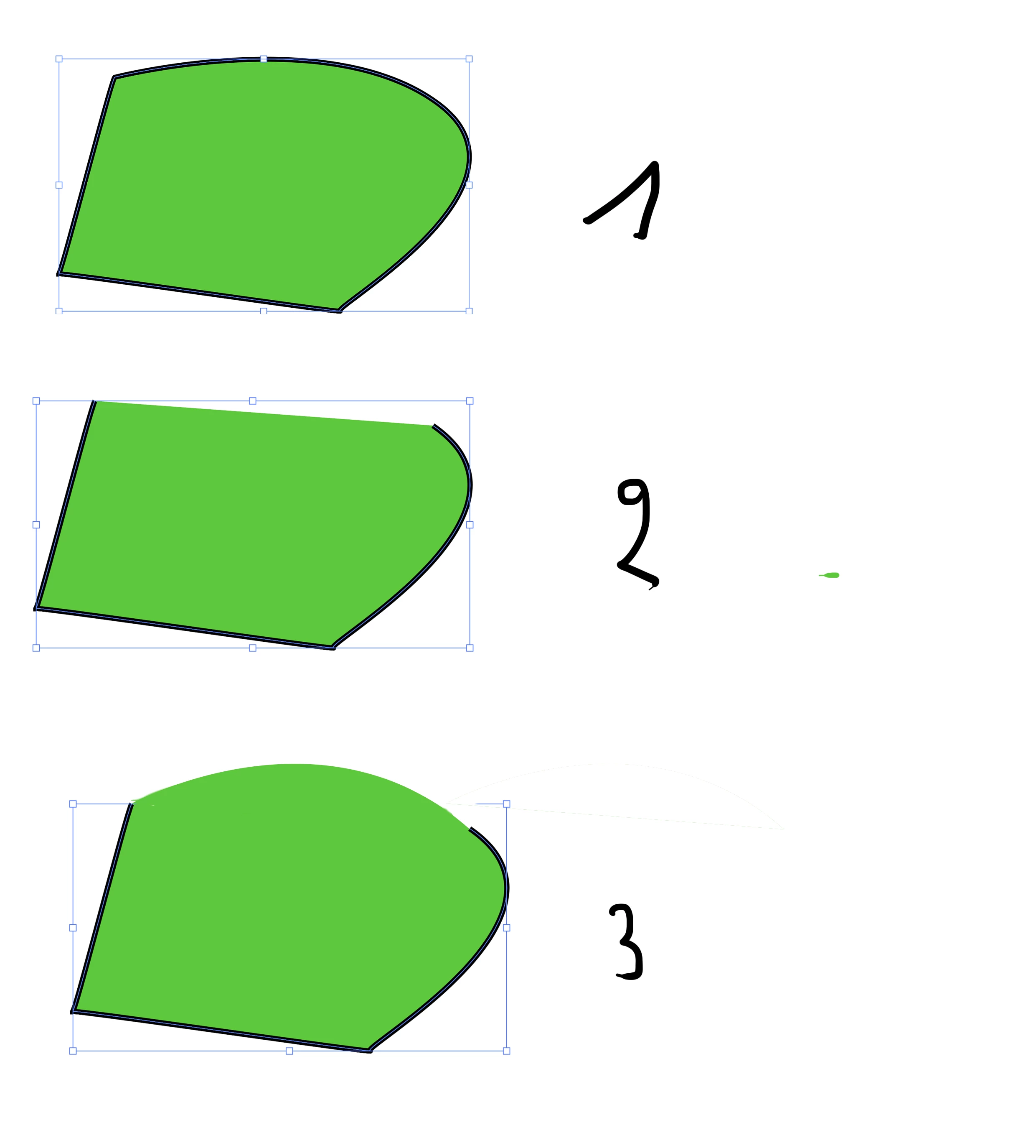

illustartor, comment garder l'arrondi de la forme quand on supprime le tracé
De 1 passer à 3
Already have an account? Login
No account yet? Create an account
Enter your E-mail address. We'll send you an e-mail with instructions to reset your password.
