Participant
June 4, 2020
Answered

Need help Rounded corners!!!!

  • June 4, 2020
  • 2 replies
  • 1756 views

Hi everyone! Can someone help me with this for me? I write this code:

---------------------

var W= 5*72; //FRONT OF THE TRAY
var L = 4*72;
var H= 2*72;

var V=0.125*72;

var Turn= (1*72);//Short Turn
var DTurn=0.375*72;//Deep Turn
var BackTurn=0.75*72;//Turn on the back
var space=0.5*72;

//Option=1;

var Option=1

var doc = app.documents.add();
activeDocument.artboards[0].artboardRect = [0,L+(H+space)*2+V*4,W+(H+space)*2+V*4,0];
activeDocument.artboards[0].name = ('ID:' +W/72+'x'+L/72+'x'+H/72+' Thness: ' +V/72+' Point');
doc.activeLayer.name = 'Thru-Cut';
var ThrucutColor = new CMYKColor();
ThrucutColor.cyan = 88.4;
ThrucutColor.magenta = 77.1;
ThrucutColor.yellow = 0;
ThrucutColor.black = 0;
var p = doc.pathItems.add();
Center=[(W+(H+space)*2+V*4)/2,(L+(H+space)*2+V*4)/2,]
Point1=[Center[0]-W/2-V,Center[1]-L/2-V]
Point2=[Point1[0],Point1[1]-H-V]
Point3=[Point2[0]+W+V*2,Point2[1]]
Point4=[Point3[0],Point1[1]]
Point5=[Point4[0]+H+V,Point4[1]]
Point6=[Point5[0],Point5[1]+L+V*2]
Point7=[Point4[0],Point6[1]]
Point8=[Point7[0],Point7[1]+H+V]
Point9=[Point1[0],Point8[1]]
Point10=[Point9[0],Point7[1]]
Point11=[Point10[0]-H-V,Point10[1]]
Point12=[Point11[0],Point1[1]]
var Points=[Point1,Point2,Point3,Point4,Point5,Point6,Point7,Point8,Point9,Point10,Point11,Point12];
for(i=0;i<Points.length;i++){
pathcut = p.pathPoints.add();
pathcut.anchor = Points[i]
pathcut.pointType = PointType.CORNER;
pathcut.leftDirection = pathcut.anchor
pathcut.rightDirection = pathcut.anchor
}
pathcut = p.pathPoints.add();
pathcut.anchor = Point1
pathcut.pointType = PointType.CORNER;
pathcut.leftDirection = pathcut.anchor
pathcut.rightDirection = pathcut.anchor
p.strokeColor= ThrucutColor;
p.closed = true;
p.filled = false;


------------

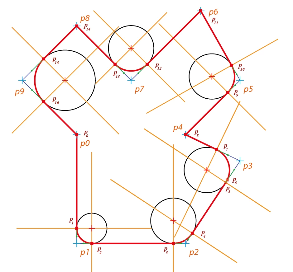
I have the drawing object like the picture.

I would like to rounded some corners with different radius 30pt on 2 corners and 50pt on another  like anothe picture.

 Actually, I found another code what can help me do that but it take time and have to run manually by selecting the corners and run this code:

https://gist.github.com/WELZ-gh/fcbf311cf504a001577d8d424336e592


So somebody can help me add in the code,what I have wrote to make, to help it run automatically without selecting like what I have to do right now.


Thank for your help!

This topic has been closed for replies.
Correct answer renél80416020

Bonjour à tous!
Comme indiqué dans le message précédent je viens de tester la première version du script arrondi angle.jsx.

Ce dernier trace un objet (pathItem) à partir de sont chemin composé de segments de droite inclus dans le script avec la particularité d'y insérer des arcs de cercle tangents à l'emplacement de sommet.
Avec en option la matérialisation des centres sous la forme d'une croix (+).

Pour signifier les arcs de cercles on utilise un tableau à plusieurs dimensions où chaque élément doit comporter:

[rayon,[liste des points],sens]
    rayon en pts
    liste ordonnée des points concernés
    sens 1 trigonométrique, 0 horaire

Exemple://Définition des arrondis à effectuer
  var lister = [];               // Respectez l'ordre
      lister[0] = [20,[1],1];    // rayon de 20pt au point 1, sens trigo
      lister[1] = [30,[2,3],1]; // rayon de 30pt aux points 2 et 3, sens trigo
    ou
  var lister = [[20,[1],1], [30,[2,3],1]];

Le reste est transparent pour l'utilisateur

Un exemple (voir pdf)

.

Remarque: On peut envisager des améliorations (choix de l'unité, agir sur un objet sélectionné qui sera copié et remplacé, utiliser un texte sélectionné représentant le tableau lister[] à utiliser, etc)


Lien pour fichier .pdf de quatre exemples.
https://share.orange.fr/#2OMP1d5S652c61d7d49e

de elleere


2 replies

renél80416020
renél80416020Correct answer
Inspiring
June 19, 2020

Bonjour à tous!
Comme indiqué dans le message précédent je viens de tester la première version du script arrondi angle.jsx.

Ce dernier trace un objet (pathItem) à partir de sont chemin composé de segments de droite inclus dans le script avec la particularité d'y insérer des arcs de cercle tangents à l'emplacement de sommet.
Avec en option la matérialisation des centres sous la forme d'une croix (+).

Pour signifier les arcs de cercles on utilise un tableau à plusieurs dimensions où chaque élément doit comporter:

[rayon,[liste des points],sens]
    rayon en pts
    liste ordonnée des points concernés
    sens 1 trigonométrique, 0 horaire

Exemple://Définition des arrondis à effectuer
  var lister = [];               // Respectez l'ordre
      lister[0] = [20,[1],1];    // rayon de 20pt au point 1, sens trigo
      lister[1] = [30,[2,3],1]; // rayon de 30pt aux points 2 et 3, sens trigo
    ou
  var lister = [[20,[1],1], [30,[2,3],1]];

Le reste est transparent pour l'utilisateur

Un exemple (voir pdf)

.

Remarque: On peut envisager des améliorations (choix de l'unité, agir sur un objet sélectionné qui sera copié et remplacé, utiliser un texte sélectionné représentant le tableau lister[] à utiliser, etc)


Lien pour fichier .pdf de quatre exemples.
https://share.orange.fr/#2OMP1d5S652c61d7d49e

de elleere


CarlosCanto
Community Expert
Community Expert
June 4, 2020

Hi dieptong, I would make this with different approach. I would make basic shapes on top of each other and join them with path finders.


// make dieline with mixed sharp and rounded corners
// carlos canto // 06/04/2020
// https://community.adobe.com/t5/illustrator/need-help-rounded-corners/td-p/11182904?page=1

function main() {
    var inches = 72;

    var W = 5 * inches; //FRONT OF THE TRAY
    var L = 4 * inches;
    var H = 2 * inches;
    var V = 0.125 * inches;

    var space = 0.5 * inches;

    // inicial origin
    var x = 0 + space;
    var y = 0 - space;

    var left = x;
    var top = y-H - V;
    var width = H*2 + W + V*4;
    var height = L + V*2;
    var r = 15;

    var idoc = app.documents.add(DocumentColorSpace.CMYK, width + space*2, H*2 + L + V*4 + space*2);
    app.coordinateSystem = CoordinateSystem.ARTBOARDCOORDINATESYSTEM;
    
    var igroup = idoc.groupItems.add();

    // MAKE 1 ROUNDED RECTANGLE AND 1 REGULAR RECTANGLE HALF THE WIDTH ON TOP TO COVER THE RIGHT SIDE
    var ipath = igroup.pathItems.roundedRectangle(top, left, width, height, r, r);

    // make a regular rectangle on top
    ipath = igroup.pathItems.rectangle(top, left+width/2, width/2, height);


    // MAKE 1 ROUNDED RECTANGLE R=50 AND TWO REGULAR RECTANGLES ON TOP TO COVER THE LEFT AND BOTTOM SIDES
    left = x + H + V;
    top = y;
    width = W + V*2;
    height = H*2 + L + V*4;
    r = 25;

    // make horizontal rounded rectangle
    ipath = igroup.pathItems.roundedRectangle(top, left, width, height, r, r);

    // make a regular rectangle on top
    ipath = igroup.pathItems.rectangle(top, left, width/2, height);

    // make another regular rectangle to cover the bottom part
    ipath = igroup.pathItems.rectangle(top-height/2, left, width, height/2);

    // APPLY UNITE PATHFINDER EFFECT AND EXPAND APPEARANCE
    igroup.selected = true;

    app.executeMenuCommand('Live Pathfinder Add');
    app.executeMenuCommand('expandStyle');
    app.executeMenuCommand('ungroup');
}
main();


dieptongAuthor
Participant
June 14, 2020

Hi CarlosCanto and everyone!

Thanks so much for your help, but it can't fix my struggle in some cases. For example that how do I rounded some corners with the angle less or more than 90 degrees. Like these with each one has 10pt, 20pt and 30pt corners.


---------------------

var W= 5*72; //FRONT OF THE TRAY
var L = 4*72;
var H= 2*72;

var V=0.125*72;

var Turn= (1*72);//Short Turn
var DTurn=0.375*72;//Deep Turn
var BackTurn=0.75*72;//Turn on the back
var space=0.5*72;

//Option=1;

var Option=1

var doc = app.documents.add();
activeDocument.artboards[0].artboardRect = [0,L+(H+space)*2+V*4,W+(H+space)*2+V*4,0];
activeDocument.artboards[0].name = ('ID:' +W/72+'x'+L/72+'x'+H/72+' Thness: ' +V/72+' Point');
doc.activeLayer.name = 'Thru-Cut';
var ThrucutColor = new CMYKColor();
ThrucutColor.cyan = 88.4;
ThrucutColor.magenta = 77.1;
ThrucutColor.yellow = 0;
ThrucutColor.black = 0;
var p = doc.pathItems.add();
Center=[(W+(H+space)*2+V*4)/2,(L+(H+space)*2+V*4)/2,]
Point1=[Center[0]-W/2-V,Center[1]-L/2-V]
Point2=[Point1[0],Point1[1]-H-V]
Point3=[Point2[0]+W+V*2,Point2[1]+72]
Point4=[Point3[0],Point1[1]+72*3]


var Points=[Point1,Point2,Point3,Point4];

for(i=0;i<Points.length;i++){
pathcut = p.pathPoints.add();
pathcut.anchor = Points[i]
pathcut.pointType = PointType.CORNER;
pathcut.leftDirection = pathcut.anchor
pathcut.rightDirection = pathcut.anchor
}
pathcut = p.pathPoints.add();
pathcut.anchor = Point1
pathcut.pointType = PointType.CORNER;
pathcut.leftDirection = pathcut.anchor
pathcut.rightDirection = pathcut.anchor

p.strokeColor= ThrucutColor;
p.closed = true;
p.filled = false;

-----------------------


Thank you so much!

renél80416020
Inspiring
June 14, 2020

Hi dieptong!

Cest tentant, mais les arcs ne sont pas de véritables arcs de cercle.

J'ai réalisé le script que tu demandes mais je n'ai pas le droit de le transmettre car Round Any Corner.js
// Copyright(c) 2005 Hiroyuki Sato

Par contre je peux faire un script qui trace les segments dans l'ordre, que ce soit rectigne ou arrondi.

Pour obtenir de vrais arcs de cercle, mais cela impose de calculet le point de départ des arcs et l'amplitude.

Dans le cas du dessin précédant, c'était simple:

Voilà le chemin en mode relatif


  var r1 = 50;
  var r2 = 30
  var Points = [[space+H+V,space+H+V],
                [0,-(H+V)],
                [W+V*2,0],
                [0,H+V],
                [H+V,0],
                [0,L+V*2],
                [-(H+V),0],
                [0,H+V-r1],
                ["a",90,r1,1],
                [-(W+V*2),r1],
                [0,-(H+V)+r2],
                ["a",90,r2,0],
                [-(H+V)+r2,-r2],
                ["a",90,r2,1],
                [-r2,-(L+V*2)]];


"a" pour arc
90 amplitude en degré

1 sens trigo 0 sens horaire.

Au plaisir