- Home
- Illustrator
- Discussions
- Drawing a series of connected straight lines by le...
- Drawing a series of connected straight lines by le...
Copy link to clipboard
Copied
AI CC 2017.1.0
I'm looking for a way of drawing a series of connected straight line segments, each with a bearing (compass direction) in degrees and a length. In some cases, these will form a closed irregular polygon (correct term?). In other cases, there is no closure.
People familiar with real-estate documents will recognize this as drawing representations of U.S. legal descriptions of properties and boundaries. Yep.
I tried the obvious method: use the Line Segment ("/") tool repeatedly. For the bearing in legalese "South 44 degrees 29 minutes east" first I discard the minutes. South is 270°, so I calculate (270 - 44) and enter the result as the angle. My scale is 1mm = 100 ft, so I enter "3.2mm" as the length. (Setting the default "general" units to mm helps this along.)
I'm still working out how to specify the endpoint of segment 'n' as the beginning of segment 'n+1'. Eyeballing is slow and inaccurate. I haven't figured out how to tell the Line Segment tool to use the last-defined path end, or the current sold handle as the starting point for the next segment. (Is there a way? Suggestions welcome!)
Is there a better way to drawing a series of connected straight line segments?
Is there a way to distinguish one segment from another? It is REALLY easy to get lost, especially when successive segments are very similar. ("Did I just draw segment 10 or segment 11?") It is no fun starting over. A visible dimension, or a slant length? (Window-->Info gives only horizontal and vertical size.) A plug-in?
Double extra credit if this can be accomplished by some form of scripting. I can hack JS to do this if someone will get me started. (My JS experience is solely with DW.)
I've got a small number of these to do, about 30 of them, from 5 to 20 segments each. I'd like to find a way to use AI to do the work. Clearly if I did this every day, I'd switch to a specialized land-management app.
TIA
Henry
 1 Correct answer
KG and BA:
This method seems to be working for me now: "Get" the Line Segment Tool from the palette, place the cross cursor at the start location, enter angle + length, and hit "OK" to draw S1. At this point the cross cursor is still visible, i.e. still have the Line Segment Tool. Click the cursor on the endpoint of S1, enter angle + length... etc. This is exactly the behavior I would expect. "Sticky" tool selection enabling "chained" function.
This didn't work before. Why? I don't know
...Explore related tutorials & articles
Copy link to clipboard
Copied
Regarding the line tool.
Make sure shape widgets are hidden-
Draw a line with the line segment tool
and click the icon Hide Shape Widgets, at the top of screen

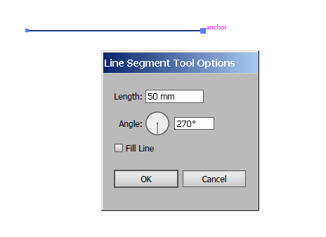
Next , hover the mouse at the end you want to continue from , and click when you see anchor.
the options box opens enter what you need and OK.
Etc
Copy link to clipboard
Copied
RY:
Thanks for your response. Unfortunately, I can't get your method to work. When I click on the anchor to draw the second segment, I get a new Line Segment dialog, just as I should, but when I enter the new length and angle, then click "OK", the 1st segment disappears and the 2nd segment appears. Maybe there's another step you assume but I don't.
Is "Hide Shape Widgets" part of the procedure for drawing _each_ segment, or just a set-up before drawing multiple segments? If hovering at that point gives the tooltip "Show Shape Widgets", I think that indicates the set-up is correct and need not be worried about, correct?
Thanks,
Henry
Copy link to clipboard
Copied
Not familiar with that type of diagram. Can you show a couple of examples of what you're trying to create?
Copy link to clipboard
Copied
BA:
Thanks for your response.
Here's a schematic map. (I've never posted a graphic before, so I hope this works.)
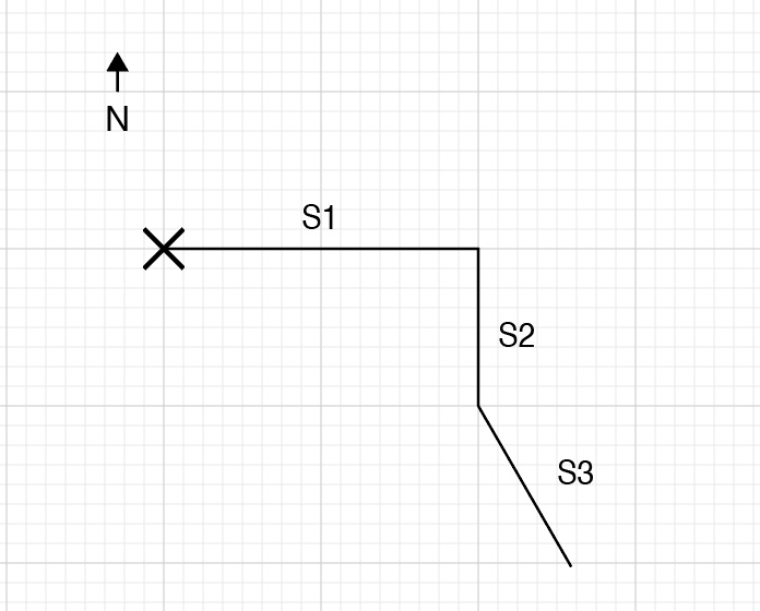
North is at the top. "X" represents the starting reference point, which –for convenience– I've placed at a major grid intersection.
S1 – the first segment – goes from the starting point, 20 units East
S2 – the second segment – goes from the end of S1, 10 units South
S3 – the third segment– goes from the end of S2, (I dunno) 24 units at 300° (AI reference) (In legalese, 30° East of South).
... and so on.
Notes:
• the segment labels don't exist in the original data; I've added them for this description.
• the final shape may be closed (for a land plot) or open (for a boundary).
• a real map wouldn't/couldn't be drawn on a standard grid, because real boundaries often don't fall on grid intersections, major or minor.
• real segments would have fractional lengths.
• I forgot what length I entered to draw S3 with the Line Segment tool, so I'm guessing. I can't find a way to directly measure the length of this line after OK-dismissing the Line Segment dialog; managing a 20-segment boundary would be MUCH easier if I get do some kind of get-info for the length of any single segment.
Thanks,
Henry
Copy link to clipboard
Copied
Thanks. Still not sure I understand so will give some general suggestions.
If you select just one end point with the Direct Selection tool, you will see the X and Y position of that point.
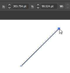
When you draw a new line segment, you can select it with the black Selection tool. In the Transform panel, click on the Reference Point icon in the upper left of the panel to specify from which corner you want the measurements, and type in the same X and Y measurements as the point you are connecting to, the one you previously selected with the Direct Selection tool.
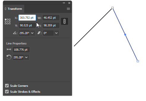
To find out the length of a line, open the Document Info panel. In the flyout menu, select Object.
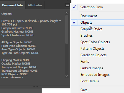
I hope this helps.
Copy link to clipboard
Copied
As far as the first line disappearing when you create a new line, you need to deselect the first line before creating another line.
Copy link to clipboard
Copied
https://forums.adobe.com/people/Barbara+Ash schrieb
As far as the first line disappearing when you create a new line, you need to deselect the first line before creating another line.
I've never experienced that behaviour before. In your version of Illustrator, do you really have to deselect a segment drawn with the Line Segment tool to prevent it from getting deleted when you draw another line segment with the same tool?
We are actually talking about using the Line Segment tool, aren't we?
Copy link to clipboard
Copied
The only other reason I can think of for the first line 'disappearing' is that it possibly has to stroke color or has a stroke of zero points.
Hen3ry, if that is happening for you, choose View > Outline to see if the first line is there.
Copy link to clipboard
Copied
It was Henry who said his first line disappeared, when he added a 2nd-
agree he probably had the stroke set to none.
Barbara looks like you have the shape widgets on in your example , that's why you need to deselect first, to continue drawing , otherwise the selected line just rotates instead of allowing adding a new one

Copy link to clipboard
Copied
KG and BA:
This method seems to be working for me now: "Get" the Line Segment Tool from the palette, place the cross cursor at the start location, enter angle + length, and hit "OK" to draw S1. At this point the cross cursor is still visible, i.e. still have the Line Segment Tool. Click the cursor on the endpoint of S1, enter angle + length... etc. This is exactly the behavior I would expect. "Sticky" tool selection enabling "chained" function.
This didn't work before. Why? I don't know. I can't reproduce my prior results, but if memory serves, the cursor was reverting to a select arrow after drawing the first segment. Is there something I'm totally missing about tool selection? If so... well ... D'oh! Sorry to bother you all about this.
Thanks,
Henry
Copy link to clipboard
Copied
Not sure if I understand correctly, but to me it sounds as if your main issue is to find a method to accurately hit end points of path segments with the Line Segment tool.
Have you already tried to turn on Smart Guides (see View menu) in order to get visual feedback and precise snapping when the Line Segment tool is hovering over the anchor points?
Copy link to clipboard
Copied
KG:
Thanks for your suggestion. I enabled Smart Guides, and adjusted its preference settings for all cues but Construction Guides "on".
Using the Line Segment tool, I drew two distinct, similar-length line segments with about 20° difference in inclination. (That's fairly typical of the actual data.) I selected one of the segments and attempted to place its endpoint on an endpoint of the other. I watched for cues from Smart Guides. I get nothing.
Is Smart Guides truly enabled? I drew a small rectangle, selected one of the line segments, and attempted to align one of its endpoints to one of the vertexes of the rectangle. I get horizontal and vertical alignment cues and the text "intersection" appears when the endpoint falls on the target vertex. So, yes.
Thanks for reminding me about Smart Guides, which --now I recall-- can be very handy in some situations, but it seems that joining "similar" line segments doesn't provide it with enough data to work with.
Thanks,
Henry
Copy link to clipboard
Copied
Smart guides can be extremely handy, but not always.
With smart guides on, you should be getting a label like this, giving you the x and y position, when moving the end point of a line to the end point of another line.
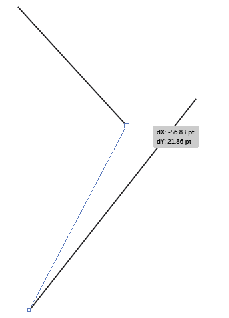
Rather than moving a line, if you have drawn a line and want to start the next line at the end point of that line you should see a label like this when your cursor is over the end point: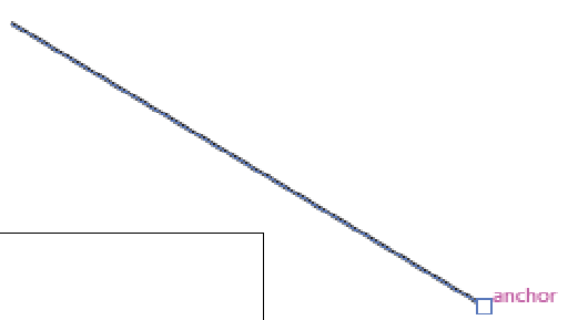
Copy link to clipboard
Copied
BA:
Thanks, that's what I see ... I think.
All:
Thanks for your patience. I think I've got it now.
Thanks,
Henry
