Copy link to clipboard
Copied
Question: With the pen tool, is there a way in Illustrator to set (or at least see) the angle between two consecutive lines as I'm drawing a shape, when the corners are not even degrees (90, 45, 30, etc)?
For example, I want to draw a line segment to a certain length, turn the corner by 91.6 degrees, draw the next line, make a 44.7 degree turn, and so on.
In the info palette, Illustrator shows me the distance and angle of my cursor from the last point drawn in real time as I'm drawing, which is very helpful. However, the angle shown is only relative to the artboard, meaning 0 degrees is always to the right, 90 up, 180 left, and 270 down), and not in relation to the angle of the last line I drew. The new dimension tools let me measure those angles after I've drawn them, but I can't fix one angle in a closed shape without ruining the two adjacent ones.
Why I'm asking:
My shop makes back-printed tabletop mats that have to be cut to fit the tabletops they're being made for. These tables are custom made, have complex shapes, and are all slightly different. I have to draw the cut paths for them in Illustrator to use with our milling/cutting plotter. I use a tape measure and a digital angle finder to measure, The angles are basically never angles I could constrain to. Replicating my measurements as a cut path is currently ultra tedious and error-prone, but easily solved if I could draw the angles I measured.
But Ken,
If you are ready for a different approach right from the tabletop measurements, you can do it more easily and I believe more accurately by triangulation as follows, Smart Guides still being your friends:
0) Start by mesauring the original length along with the distance from the start of the original line to the end of the following line instead of the digitally established angle;
1) Create a circle with a diameter twice the length of the first added line and snap its centre to the
...Copy link to clipboard
Copied
You may turn on smart guides (View menu) and enable construction guides with custom angles in the Smart Guides section of the application preferences.
Apart from that, can you share a sample Illustrator file with some more instructions about the cut paths you're going to create? Maybe there is an easier way to make them.
Copy link to clipboard
Copied
Thanks for the quick reply, Kurt. Can you elaborate on how you'd approach this?
I've checked on the preference box and entered my custom angles (like 91.6 and 44.7) into the Construction Guides' custom angles fields, but it seems to have no effect on either the snapping behavior or hints shown by Smart Guides. Holding shift to constrain with custom angles set seems just to revert to snapping at 45 degree increments. Hopefully, I'm just missing something?
Copy link to clipboard
Copied
Can you show a screenshot of your smart guides settings?
Copy link to clipboard
Copied
Here they are. Note, I also tried several different settings with the snapping tolerance.
Copy link to clipboard
Copied
This is what I see when drawing with the Pen tool while using two of your construction guide settings.
Isn't that what you're looking for?
Copy link to clipboard
Copied
Unfortunately, no. Those hints show the angle of each line relative to the artboard (where right is always 0 degrees), which is also shown live in the bottom right of the info box:
What I'm looking for is to be able to set (or at least see) the angle between the segment I've just drawn and the one I'm drawing, as I can currently only see using the measure tool afterward:
Copy link to clipboard
Copied
I see, sorry, I misunderstood your request. What you want is currently not available in Illustrator.
Again, you may want to share a sample Illustrator file with instructions about the cut paths. There may be a different and probably easier approach to create the cut paths.
Copy link to clipboard
Copied
I'm open to suggestions.
The basic challenge is that the tabletops are unique shapes, often with more than four sides due to overleafs and notches. They're trimmed by hand to mount flush into existing locations, which means they aren't ever square and the mats can only be measured after installation. While I do get accurate measurements of each the sides with a measuring tape, and an angle finder shows the exact angle of each corner, I have to fudge all that into illustrator and it's currently trial and error since I can't predict the angles of the corners as I'm drawing them.
As for the cut path itself, it's only a simple, 1pt path in a shape matching the tables' outline. It's set to a specific spot color that our print server can read. When we print a mat, the print server sends the cut path to our plotter and prints in some alignment marks. After loading the print into the plotter, the plotter registers itself to the print using the marks and then traces the line with a drag knife or milling bit.
Copy link to clipboard
Copied
Thanks for the elaboration, Ken.
To check if there are alternative ways to create the cut paths, it would be helpful if you could provide a sample Illustrator file (ideally with a sample cut path). This way, it would be easier to inspect what may be possible, and what not.
Copy link to clipboard
Copied
The .eps file for an example mat is attached (for some reason, the forum would not allow me to post it as .ai). There is a Cut layer with the plotter's cut path on it, and an Artwork layer for the printed graphics to go including overly-generous bleed. I set it up quickly for an example, so the angle measurements in the file are all square, but actual measurements taken from the table top (imperial inches) are here:
This one had a few more regular corners than usual.
Copy link to clipboard
Copied
Thanks for the sample file, Ken.
In that quite simple case I guess you already know that you can create the cut path by just selecting the yellow object and doing an Offset Path with negative values (see Object menu > Path > Offset Path).
In case your real world files contain more complex constructions, you may share another sample file.
Copy link to clipboard
Copied
Sorry, to clairfy:
- The graphic layer/offset/bleed aren't really related to the problem, they're just in the file for example.
- The hand measurements are on a drawing that's not in any kind of scale, so I can't just scan and trace the shape
- The example cut file doesn't match the table, even though it was built using the length measurements shown
Restating the problem:
How can I draw the cut path in Illustrator to accurately match the live measurements?
With corners that have angles like 89.7 degrees, and sides that have lengths like 58.125 inches, I can't find a way to accurately draw a cut path with matching dimensions.
Mainly, it's because I can't gauge the angle of a corner I'm drawing until after it's drawn. Then, it can't easily be corrected - as I mentioned earlier, fixing one angle messes up the two adjacent corners and the lengths of those connecting sides.
The cut path in my example file has sides with lengths that are extremely close to the live measurements, but the angles are off. Even though the angles are different by tenths of a degree, a mat cut from this file under- or overlaps the table in different places by a finger-width or more, and cannot be laid down.
Perhaps this helps?
Copy link to clipboard
Copied
Sometimes one is talking about things based on completely different assumptions about the actual requirements. And even worse, sometimes I'm a bit slow-witted.
But based on your sample file, may I ask again:
- You select the yellow filled object
- You go to the Object menu > Path > Offset Path command
- In the Offset Path dialog you set a negative offset value (let's say (minus) 30 mm)
- You remove the fill colour and apply a stroke with the spot colour called "Cut"
Isn't that what you are looking for?
Copy link to clipboard
Copied
No, sorry, it's not what I'm looking for, but I do appreciate your sticking with me on this and trying to help!
The yellow filled object is just a placeholder for where some production graphics would eventually go, and doesn't really matter for the example. In a real production file, I agree that , yes, there would be a bleed set up using an offset.
However, here, the Cut layer does actually have a path with a "Cut" spot color on the stroke, but it's the wrong shape despite having the side lengths mostly spot on. The problem is drawing this cut path in the correct shape from measurements. Not having a way to draw corners with specific angles that correspond to the corner (rather than the artboard) is the underlying reason.
Copy link to clipboard
Copied
Thanks for the ongoing clarification, but I'm afraid that I do not really understand your final goal without taking a look at a real production file.
Perhaps someone else may understand it better and can assist you.
Copy link to clipboard
Copied
Thanks, Kurt. It can be really hard to get to the root of something like this over a forum post, and I thank you for your noble efforts! However, let me try one last time at clearing up the confusion:
1) This is a real production file.
2) The cut path has to be drawn before the artwork on these mats, because the final product must exactly fit an existing, real table top's shape.
3) The hand-written measurements I scanned above are from an actual table top and were measured using a tape measure and angle finder. The cut path has to match that.
4) The .eps file was drawn in Illustrator using the hand measurements above, but the cut path is inaccurate for the table despite the lengths closely matching.
5) The reason the cut path is inaccurate is because the angles don't match the hand measurements, and I don't know a way to gauge that while drawing them.
6) The yellow shape is only a placeholder for the production artwork. It can be safely ignored for this example, as it would be added after the cut shape is correctly set up.
Copy link to clipboard
Copied
Ken,
It seems that I understood the task.
In addition to the two ways described separately, the latter based on triangulation being the one I should use myself any time, a general comment:
Such tasks can always be done in fundamentally the same way as in the workshop or better with the help of Illy (job description Adobe Illustrator) owing to her skills, and she is always eager to help.
And often, going through how you would do/draw it with the help of Illy can lead to a better way (to start and also end) in the workshop.
Copy link to clipboard
Copied
Ken,
The following is a way to proceed with what you have, but I should prefer the quite different approach described below.
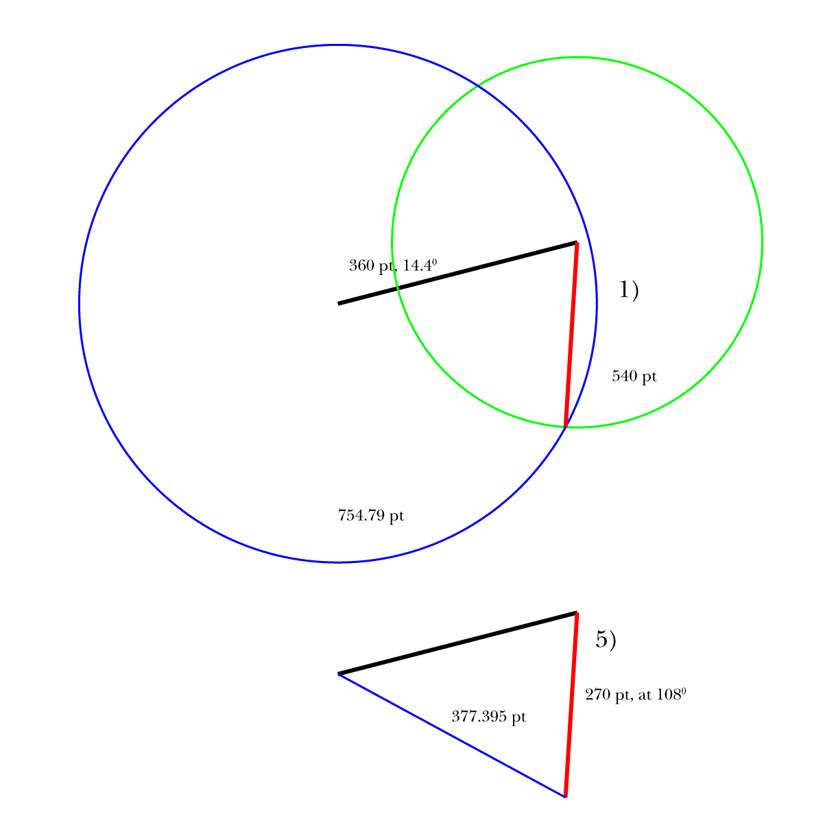
Based on your description in your 108 degrees sample, presuming you have a first line of a certain length and direction (shown below at 360 pt and at 14.4 degrees), and you wish to add a second line at its end with a certain (other) length at a certain angle relative to it (shown in red below at 270 pt and eventually at 108 degrees anticlockwise), you can, Smart Guides being your friends:
1) With the Line Segment Tool, Clci the Artboard and insert the desired length and angle (270 pt and arbitrary angle set to 0 degrees here);
2) ClickDrag either end of the red line with the Selection Tool to snap to the end of the original line;
3) Switch to the Rotate Tool and Alt/OptionClick the coinciding end Anchor Points, then Rotate the red line to snap to the original;
4) Almost as in 2) ClickDrag the inner end of the red line to snap the end of the original line;
5) Almost as in 3) Switch to the Rotate Tool and Alt/OptionClick the coinciding end Anchor Points, then insert the desired rotation (-180 degrees).
This will be as accurate as you measurements.
You can continue in the same way till fully done, then join the lines.
Click to see in full, Click again to get closer
Copy link to clipboard
Copied
But Ken,
If you are ready for a different approach right from the tabletop measurements, you can do it more easily and I believe more accurately by triangulation as follows, Smart Guides still being your friends:
0) Start by mesauring the original length along with the distance from the start of the original line to the end of the following line instead of the digitally established angle;
1) Create a circle with a diameter twice the length of the first added line and snap its centre to the end of the original line (540 pt shown in green), then Create a circle with a diameter twice the distance to the end of the first added line (754.79 pt shown in blue), then with the Line Segment Tool ClickDrag from the intersection of the two circles to the centre of the green circle/the end of the original line.
The distance for the blue circle is shown as the blue line in a copy of step 5) from the previous post.
In many cases you can increase the accuracy, sometimes significantly, by A) Choosing the order of corners established more freely, and B) Use large distances, and C) establish corners by choosing distances as close to perpendicular as possible, and D) check the shape by additional establishment of distances, thus basically using triangulation by distances; you can also E) use right angles when applicable and suitable.
Using the full tabletop in your other post as a sample, you can start with the top left and right corners to establish the bottom middle corner of the full tabletop in your other post, thereby staring with a large triangle, then use the top corners again to establish the inner corner, then use the inner corner along with each of the top corners to establish the middle corners in each side, and end with the lower left corner established by the inward corner and the left middle corners; and you can use the disrtance between the bottom middle corner and the lower left corner to check the position of the latter, and similarly the check the position of the middle right corner by its distance from the bottom middle corner.
As you can see, this way is far simpler, and I am sure the it is rather more accurate to measure the most suitable distances than the angles between adjacent lines/sides, further increased by additional distances (and/or right/known angles). Working with Illy, the large circles form no inconvenience.
This is the way I should choose any time, also in case everything was to be made in the workshop with manual cutting.
Click to see in full, Click again to get closer
Find more inspiration, events, and resources on the new Adobe Community
Explore Now