Copy link to clipboard
Copied
I need to recreate this dial and I've learned how to create evenly spaced tick marks within a circle, but this is an ellipse. Here, I attempted to draw two ellipse then used the scissors to cut them to size. Then I used the line tool and drew each of the tick marks. Then I adjusted the weights of each tick. This is not a good method because the end ticks are not meeting the ends of the ellipse perfectly, leaving a tiny bit of tick mark outside the ellipse. There must be a better way to do this. Here is what I ended up with:
But this is what I need to create:
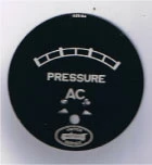
(I only need to create the arched part with tick marks of this dial)
Any help is appreciated, but please note that I am familiar with only the very basics of illustrator, I simply don't do this type of work often enough to completely understand the software.
Thanks!!!!
Jber,
If you wish to have the tick marks follow an ellipse and at the same time have constant widths (two different widths), you may:
0) Lock the image of the dial;
1) Create the thickest tick mark and move a copy to the right, then create a one step blend;
2) Create the thinnest tick mark and move a copy to the right, then create a five steps blend;
3) Create the two ellipses corresponding to the two arcs, then create a one step blend and Object>Blend>Expand to get a midway ellipse;
4) With the midwa
...Copy link to clipboard
Copied
Jber,
I believe it is (close enough to be considered) a circle, at least when taking the irregularities into account. The two outermost tick marks seem to point to the largest circle below AC, and if you measure the distance from that to the ends and to the middle of the arc, I believe you will find that they are just about the same.
Copy link to clipboard
Copied
I would draw this straight, then use
Object >> Envelope Distort >> Warp
Copy link to clipboard
Copied
And live with the widening tick marks, Mike?
Copy link to clipboard
Copied
Mike, thank you very much I actually can see where your method could come in handy in some situations, and I really really really dumb for asking this, but when you say "I would draw this straight" do you mean that you used the line tool, created the upper and lower horizontal lines, then used the line tool again to make the tick marks?
Copy link to clipboard
Copied
Yes draw the graphic straight as in the top half of my screenshot, the bottom half shows the graphic distorted.
I drew a rectangle, then with the hollow arrow tool clicked on the middle of a line, copied and used CMD F to paste in front, then increased teh line width. OPtion dragged a few copies adn used distribute in the align palette.
Copy link to clipboard
Copied
Jber,
If you wish to have the tick marks follow an ellipse and at the same time have constant widths (two different widths), you may:
0) Lock the image of the dial;
1) Create the thickest tick mark and move a copy to the right, then create a one step blend;
2) Create the thinnest tick mark and move a copy to the right, then create a five steps blend;
3) Create the two ellipses corresponding to the two arcs, then create a one step blend and Object>Blend>Expand to get a midway ellipse;
4) With the midway ellipse Object>Path>Add Anchor Points a few times (see below), and copy the midway ellipse;
5) Select the original midway ellipse and the thin blend and Object>Blend>Replace Spine;
6) Select the copy midway ellipse and the thick blend and Object>Blend>Replace Spine.
Now you should have the whole dial with the thickest tick marks on top of the thinnest ones on top of the elliptic arch set.
If you wish to extend the thick tick marks upwards, you may select that blend and:
7) Object>Blend>Expand;
8) Select each of the thick tick marks and select the appropriate bottom Reference Point in the Transform palette ((Right for left, Center for centre, Left for right), then multiply the H value by the deisred amount and click Ctrl/Cmd+Enter to make them a bit longer up/outwardly.
The Object>Path>Add Anchor Points in 4) is to get a even distribution of the thin tick mark blend (not necessary for the thick tick marks blend because it only has one step).
Copy link to clipboard
Copied
Thank you very much Jacob! This all seems like stuff I understand, but I won't get a chance to try out your method till the morning. If I have any problems with it, I'll post back.
Much appreciated.
Copy link to clipboard
Copied
You are welcome, Jber. I should mention that the dial photo shows a total of four thick tick marks, in which case you should make a two step blend in 1).
I believe Mike meant that you can create the straight version in whichever way you want, then Arc it (hopefully not Argh it).
To correct what I said before, this may tick marks with thicknesses that grow upwards, corresponding to the difference in the lengths of the curved top and bottom.
One way that results in constant thickness tick marks might be to (using Stroke>Round Cap/Join or Stroke>Projecting Cap/Miter Join or Stroke>Butt Cap and Miter Join depending on the desired end shape and length, see below):
1) Apply the Rectangular Grid Tool with the desired width and height and with 0 Horizontal Dividers and 5 Vertical Dividers;
2) Direct Select the tick marks to be thick and Ctrl/Cmd+C+F+X+C to create independent paths in front, then increase their Stroke Weight as desired, then if you want to have them extend past the grid at the top as in the photo (instead of both at the top and the bottom) use Round or Projecting Cap and move them up by half the difference in Stroke Weight (if they are 2pt and the grid is 1pt move them up by 0.5 pt), and if you want to have them fit the height of the grid use Round or Projecting Cap and decrease their length by the difference in Stroke Weight or use Butt Cap and increase their length by the difference in Stroke Weight;
decrease their length;
3) Group the grid and the thick tick marks;
4) Effect>Warp>Arc.
Copy link to clipboard
Copied
With the rectangle grid method, I attempted to replicate what you were doing, but when I got to the part where I needed to select the tick marks that would be thicker than the rest, this included both left and right sides, just like your illustration shows, but when I actually selected the left side, the entire outer rectangle frame also selected and I ended up increased the whole rectangle. What am I doing wrong here?
Thanks
Copy link to clipboard
Copied
Jber,
In post #7 I should have mentioned that you have to deselect the rectangular grid between 1) and 2) in order to Direct Select only the segments to become the thick tick marks. Without deselecting, the whole grid will remain selected.
And I should have mentioned that to select all those segments at the same time, you have to press and hold Shift while you click them (only needed from the second one one, but you can also hold Shift from the very first one).
I apologize for my forgetfulness.
Copy link to clipboard
Copied
no apology necessary, I think it's amazing that your willing to help me like this. Yes I understand about selecting and holding shift, but the thing is, when I click on the left side which is will be one off the ticks that needs to have it's stroke weight adjusted, the entire retangle is selected (not all the ticks, just the outer rectangle) I can't figure out how you got the left side and right side selected without selecting the "box" part of the it.
Copy link to clipboard
Copied
Jber,
... the entire retangle is selected (not all the ticks, just the outer rectangle) ...
This is an attempt to make sure everything is included in the crucial step 2), as an amendment of post #7 (I will amend post #4 as well, hopefully before you need it):
One way that results in constant thickness tick marks might be to (using Stroke>Round Cap/Join or Stroke>Projecting Cap/Miter Join or Stroke>Butt Cap and Miter Join depending on the desired end shape and length, see below), with the layer expanded in the Layers palette (and Smart Guides may be your friends, telling you when you when you are in the right spots):
1) Apply the Rectangular Grid Tool with the desired width and height and with 0 Horizontal Dividers and 5 Vertical Dividers;
2) Switch to the Direct Selection Tool and click an empty spot (away from the grid), then
2a) Click on the leftmost segment (somewhere in the middle away from the end Anchor Points) to select the first tick marks to be thick, then
2b) Hold Shift and click on the other segments to select the rest of the tick marks to be thick, then
2c) With all those segments selected click Ctrl/Cmd+C+F+X+C to create independent paths in front (you should be able to see them appear at the top in the Layers palette), then
2d) Increase their Stroke Weight as desired, then if you want to have them extend past the grid at the top as in the photo (instead of both at the top and the bottom) use Round or Projecting Cap and move them up by half the difference in Stroke Weight (if they are 2pt and the grid is 1pt move them up by 0.5 pt), and if you want to have them fit the height of the grid use Round or Projecting Cap and decrease their length by the difference in Stroke Weight or use Butt Cap and increase their length by the difference in Stroke Weight;
3) Group the grid and the thick tick marks;
4) Effect>Warp>Arc.
Copy link to clipboard
Copied
Hi Jacob;
Question. I got to step 3 where you said to create the two ellipses, then create a one step blend and object>Blend>Expand to get a midway ellipse;
the "expand" option under object>blend is greyed out, I'm not able to select it. Did I miss a step? This is what I got so far:
the first two lines are my two step blend for the large ticks and the 2nd two lines are my thinner ticks with the two ellipses below that.
Thanks.
Copy link to clipboard
Copied
Jber,
When you select the two ellipses and make the blend, the midway ellipse should show up between them (but just as an appearance, without the highlighting and the Anchor Points of the others), and then you should be able to expand to have the midway ellipse as an independent path in the group with the others.
Copy link to clipboard
Copied
Hi Jacob;
First let me say thanks for your patience. I feel very embarressed to have to ask for explanation on what probably seems so apparent to yourself, but...here goes.
I got to step 3 and where you said create the ellipses then object>blend>expand to get a midway ellipses. The option to "expand" was not there, I figured out that I first needed to: object>blend>make in order to get the "expand" option to show up. then I was able to move forward and create the anchor points as instructed in step 4. But in step 5 I got stopped again at your instruction object>blend>replace spine... the "replace spine" option is not available. I do have the midway ellipse selected. This is what I have:
The ellipse on the bottom is the copy that I made. Im sure that I'm missing a step in order to get "replace spine" to show up, but I don't know what.
Thanks for helping a newbie out.
Copy link to clipboard
Copied
Jber,
create the ellipses then object>blend>expand to get a midway ellipses
In full, in post #4, it was:
3) Create the two ellipses corresponding to the two arcs, then create a one step blend and Object>Blend>Expand to get a midway ellipse;
I believe I should have written the emphasized part out in full, Object>Blend>Blend Options set Spacing to Specified Steps = 1, and Object>Blend>Make.
Likewise, in 1) and 2), you should create blends for the tick marks, setting Specified Steps = 1 and 5 respectively. Only then will the replace spine option be available in 5) and 6), because it requires an actual blend with a spine to replace.
Apart from that, you have to keep the copy of the midway ellipse in place together with the original to have both the tick mark blends in the right place.
And you will have to cut the ellipses where the dial is to end (with the outermost tick marks).
Copy link to clipboard
Copied
thank you Jacob, I will try again tomorrow after work, thanks for working with me.
Copy link to clipboard
Copied
Jber,
And this is an attempt to give a (hopefully sufficiently) more complete description of the ellipse way, as an amendment of post #4 (overdoing silly things like this makes it difficult to remember to mention all the crucial steps that seem to hide somewhere in the fingers):
One way that results in constant thickness tick marks might be to (using Stroke>Round Cap/Join or Stroke>Projecting Cap/Miter Join or Stroke>Butt Cap and Miter Join depending on the desired end shape and length, see below, with the layer expanded in the Layers palette, and Smart Guides are your friends, telling you when you when you are in the right spots):
If you wish to have the tick marks follow an ellipse and at the same time have constant widths (two different widths), you may (see below):
0) Lock the image of the dial (shown as a grey area below), you may place it at X = 0 to facilitate symmetric building;
1) Create the thickest tick mark and move a copy to the right, then create a one step blend (Object>Blend Options>Specified Steps = 1, then Object>Blend>Make);
2) Create the thinnest tick mark and move a copy to the right, then create a five steps blend (Object>Blend Options>Specified Steps = 5, then Object>Blend>Make);
3) Either of two ways (in both cases make sure to make it as symmetrical as possible):
3a) Create the midway ellipse, adjusting the top of it to be midway between the two arcs (this is the first way I thought of and the way shown below), or
3b) Create two ellipses corresponding to the two arcs, then create a one step blend and Object>Blend>Expand to get the midway ellipse and delete the other two;
4) Drag horizontally with the Line Tool (hold Shift) to make a path between the two spots where the midway ellipse crosses the ends of the dial image (Smarts Guides say intersect), or just create a horizontal path and place it so it crosses the ellipse in the right spots (you can see the symmetry here);
5) With the horizontal path still selected Object>Path>Divide Objects Below;
6) Delete the lower superfluous part of the ellipse, then with the Direct Seletion Tool click the horizontal segment and delete it (only click delete once);
7) Select the remaining midway ellipse part and Object>Path>Offset Path, using half the height of the dial image (at the middle), you may retry until you have it right, this will recreate the top and bottom of the dial and also make ends;
8) Select the midway ellipse part and Object>Path>Add Anchor Points a few times (see below), and copy the midway ellipse, now you have two on top of each other, one for each of the blends;
9) Select one of the midway ellipses along with the thin blend from 2) (hold Shift to have them both selected) and Object>Blend>Replace Spine, this will make that ellipse part disappear;
10) Select the other midway ellipse and the thick blend from 1) (hold Shift to have them both selected) and Object>Blend>Replace Spine;
11) Hide/Delete the image dial.
Now you should have the whole dial with both sets of tick marks on top of the elliptic arch set. In 9) and 10) you may select on the Artboard or through the Layers palette (you can see what you are selecting in both places), and the order (and stacking order) in 1)/2) and 9)/10) can be changed.
If you wish to move/extend the thick tick marks upwards or both up and down, you may:
12) Select the thick ticks blend and Object>Blend>Expand, and then Select each of the thick tick marks and tick the appropriate Reference Point in the Transform palette (if you want to extend upwards use the bottom ones (Right for left, Center for centre, Left for right), if you want to extend both up and down use the Center one), then multiply the H value by the desired amount and click Ctrl/Cmd+Enter to make them a bit longer up/outwardly.
The Object>Path>Add Anchor Points in 8) is to get a even distribution of the thin tick mark blend (not necessary for the thick tick marks blend because it only has one step).
Copy link to clipboard
Copied
Jacob, I so very much appreciate your kindness and your tutorial. I unfortunately suffered a pc meltdown and ended up having to do a fresh install of windows. I've finally got the internet working, but none of my programs installed just yet. Needless to say it might be a few days before I get the chance to try out your tutorial. I will let you know how it goes.
Thanks again!!!
Copy link to clipboard
Copied
Jber,
I am very sorry to hear about all the troubles. I look forward to our hearing your findings.
Copy link to clipboard
Copied
Jacob;
tytyty!!! Your tutorial was great! I was able to clear up all the little problems I had with the previous instructions and all went perfectly until I got to step 9. I was able to create the entire dial and the only problem I have now is that the verticle lines are straight up and down, they are not slanting like yours do in your illustration number 9. Also, just to clarify... you said that I could add anchor points to correspond with the tick marks. So... does that mean that this method would work wheather 7 ticks were needed or 20? I would just add 20 anchor points? thank you so much for your help, I could not do this without you and it's so nice to be able to stop banging my head against a wall!
Copy link to clipboard
Copied
Jber,
the only problem I have now is that the verticle lines are straight up and down, they are not slanting like yours do in your illustration number 9.
Before creating the blend, in Object>Blend>Blend Options tick Orientation>Align to Path (sorry I failed to state that).
you said that I could add anchor points to correspond with the tick marks.
When you have a curved path that is not a circle, the Handles of the Anchor Points have different lengths, and therefore they tear at the blend so it gets uneven, unless you Object>Path>Add Anchor Points and add enough. You can see if you have far too few, with a little too few it may be tricky. One or two Anchor Points for each tick mark should be enough.
Copy link to clipboard
Copied
Yep! align to path in the blend options did the trick! thank you very much for all your patience. It was so very much appreciated and its really great that resources such as this with people such as you exist!
Copy link to clipboard
Copied
Jber,
As you knew long before this thread, I find this kind of challenge irresistible.
And as you know now, I still have to rely on amending sloppy posts (I was just reminded of it myself).
Find more inspiration, events, and resources on the new Adobe Community
Explore Now