

- Home
- InDesign
- Discussions
- Re: Modifying the Sample Crop Script in ID
- Re: Modifying the Sample Crop Script in ID

Copy link to clipboard
Copied
I need some help changing the way the sample crop marks script works in InDesign.
It works great for adding crop marks to the objects in the document, but my company needs the crop marks to be placed slightly different. The best way I can describe this is to refer to sample below. The script makes the crop marks look like item A. I need them to look like item B. Both sets show crop marks that are quarter inch long and a quarter inch away from the image. I need them to be connected like in B. and have the long side of the crop mark be the edge and not the short side like it is in A.

Ideally, we would also have the script create a text box created for text in Bell Gothic Std, bold, 9 pt, centered in between the bottom crop marks, but this is just in a perfect world. 
Any help is appreciated as I do not have the scripting knowledge to do this on my own and don't have the opportunity to learn it either.
Thank you!!
Ann
*posted this earlier in the regular indesign forum in error. my apologies for the duplicate post.


 1 Correct answer

Writing an entirely new script is easier than figgering out what to change, so:
...prevHMU = app.activeDocument.viewPreferences.horizontalMeasurementUnits;
prevVMU = app.activeDocument.viewPreferences.verticalMeasurementUnits;app.activeDocument.viewPreferences.horizontalMeasurementUnits = MeasurementUnits.POINTS;
app.activeDocument.viewPreferences.verticalMeasurementUnits = MeasurementUnits.POINTS;for (s=0; s<app.selection.length; s++)
{
b = app.selection.geometricBounds;
rightangle (b[1],b[0],-1,-1);
 17
Replies
17
17
Replies
17
Copy link to clipboard
Copied
I'm no printer, but I always thought crop marks would be interpreted like this: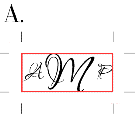
Copy link to clipboard
Copied
That's generally how they would be but these are going to be metal plates and the department wants them to be as shown in B.
Copy link to clipboard
Copied
In the dialog box that comes up when you run the script, set offset to zero?
Copy link to clipboard
Copied
No because I need an offset of .25 inches, zero would be right at the edges.
Copy link to clipboard
Copied
Your picture B gives the impression that they are right at the edges, not a quarter inch away from the edges.
I wonder if the problem here has something to do with equivocation in the way crop marks are used? I always assumed that crop marks are intended to show where the printer should cut along, not cut "up to".
Copy link to clipboard
Copied
I'm not sure how B. makes it look like the cuts are at the edges, the red line shows where the image will be cut. Of course they can cut further past the corners of each image as well. "Crop marks" may not be the correct term, but that is what the people who are cutting call them. THanks for your input and help.

Copy link to clipboard
Copied
Also I posted in the regular InDesign Forum by mistake earlier. Here is the link to the discussion that the question generated: http://forums.adobe.com/message/2178131#2178131
Copy link to clipboard
Copied
I have the same reservations about the correct placement  , but rest assured, what you ask should be quite easy to do.
I only need one single item of information. The Crop Marks script places crop marks around a certain object. Different sized objects give differently placed crop marks -- not the same size. So
- What do you have to serve as 'framework' for the crop marks? An entire image inside one single frame, that gets cut to that exact size? Separately placed objects in InDesign? An invisible frame around the entire set?
- ... (I'm pretty sure I had two questions ... can't remember what the 2nd thing was. Perhaps it was not that important.)
Copy link to clipboard
Copied
[Jongware] wrote:
I have the same reservations about the correct placement
I only need one single item of information. The Crop Marks script places crop marks around a certain object. Different sized objects give differently placed crop marks -- not the same size. So
- What do you have to serve as 'framework' for the crop marks? An entire image inside one single frame, that gets cut to that exact size? Separately placed objects in InDesign? An invisible frame around the entire set?
- ... (I'm pretty sure I had two questions ... can't remember what the 2nd thing was. Perhaps it was not that important.)
What I'll probably do is use the Place function to place 5-10 images into an ID document. I've been choosing the option to create crop marks around each individual object/frame. So there are separately placed objects of varying dimensions in the document. I am not sure what type of frame gets created when using the Place function.
Crop marks will be 1 pt thick, and .25 in (18 pt) long. And should hopefully be .25in away from the bounds of each image. And shaped in the odd shaped crop mark as shown in the image posted earlier.
I didn't think it would be that hard to modify the sample crop marks script with some knowledge of the language so I am glad someone has stepped forward to help out. Thank you!!!!
(PS-I am on vacation next week but I will be back on Monday the 24th so if I don't reply that's why. I'm definitely still interested in figuring this out!)
Copy link to clipboard
Copied
Writing an entirely new script is easier than figgering out what to change, so:
prevHMU = app.activeDocument.viewPreferences.horizontalMeasurementUnits;
prevVMU = app.activeDocument.viewPreferences.verticalMeasurementUnits;app.activeDocument.viewPreferences.horizontalMeasurementUnits = MeasurementUnits.POINTS;
app.activeDocument.viewPreferences.verticalMeasurementUnits = MeasurementUnits.POINTS;for (s=0; s<app.selection.length; s++)
{
 b = app.selection.geometricBounds;
 rightangle (b[1],b[0],-1,-1);
rightangle (b[3],b[0],1,-1);
rightangle (b[3],b[2],1,1);
rightangle (b[1],b[2],-1,1);
f = app.activeDocument.textFrames.add ();
f.geometricBounds = [b[2]+18,b[1],b[2]+36,b[3]];
f.parentStory.appliedFont = app.fonts.item("Bell Gothic Std\tBold");
f.parentStory.appliedFontSize = 9;
f.parentStory.justification = Justification.centerAlign;
f.verticalJustification = VerticalJustification.centerAlign;
}app.activeDocument.viewPreferences.horizontalMeasurementUnits = prevHMU;
app.activeDocument.viewPreferences.verticalMeasurementUnits = prevVMU;function rightangle (x,y, xsign,ysign)
{
l = app.activeDocument.graphicLines.add();
// l.geometricBounds = [y+ysign*.25, x+xsign*.5, y+ysign*.25, x+xsign*.25];
l.paths[0].pathPoints[0].anchor = [x+xsign*36, y+ysign*18];
l.paths[0].pathPoints[1].anchor = [x+xsign*18, y+ysign*18];
l.paths[0].pathPoints.add ({anchor:[x+xsign*18, y+ysign*36] });
l.fillColor = app.activeDocument.swatches.item("None");
l.strokeColor = app.activeDocument.swatches.item("Registration");
l.strokeWeight = 0.5;
l.strokeStyle = app.strokeStyles[0];
}
Copy, paste into a plain text editor (or in the ExtendScript editor that comes with InDesign). Save as "MyCustomCropmarks.jsx" (or another useful name) into your scripts folder.
The script creates the four marks and the text box as a bonus. The font should be set right -- if it errors out on that line, the name may not be correct.
Usage: select one or more of your images and double-click the script. (That's right: it also runs on more than a single image!)
Copy link to clipboard
Copied
-- an afterthought. If the text underneath should simply be the image filename (or a part thereof), I could put it in right away.
Happy holidays!
[Post-edit] Re-reading to confirm I got the details right, I spotted a tiny error. The script creates lines of 0.5 (points) thick. Simply change this line near the bottom
l.strokeWeight = 0.5; to this
l.strokeWeight = 1;
Copy link to clipboard
Copied
Thanks for the script! I'm very excited to try it.
I did fix the stroke weight, but I am getting an error message:

You mentioned using the file name as the text, would this be the filename of the placed object? If so, that would be great. We would still need to add some slashes and other information by hand, but adding the filename would save that much more time!
Copy link to clipboard
Copied
Had a good vacation? Me, I've done nuffin' but work ... 
Solving that one error you pointed out just led to another, and another, and then again ... All really tiny, tiny changes from CS to CS4. So here is a complete new script -- by the way, it now also fills in the image name.
prevHMU = app.activeDocument.viewPreferences.horizontalMeasurementUnits;
prevVMU = app.activeDocument.viewPreferences.verticalMeasurementUnits;
app.activeDocument.viewPreferences.horizontalMeasurementUnits = MeasurementUnits.POINTS;
app.activeDocument.viewPreferences.verticalMeasurementUnits = MeasurementUnits.POINTS;
for (s=0; s<app.selection.length; s++)
{
 b = app.selection.geometricBounds;
 rightangle (b[1],b[0],-1,-1);
 rightangle (b[3],b[0],1,-1);
 rightangle (b[3],b[2],1,1);
 rightangle (b[1],b[2],-1,1);
 f = app.activeDocument.textFrames.add ();
 f.geometricBounds = [b[2]+18,b[1],b[2]+36,b[3]];
 f.parentStory.appliedFont = app.fonts.item("Bell Gothic Std\tBold");
 f.parentStory.pointSize = 9;
 f.parentStory.justification = Justification.centerAlign;
 f.textFramePreferences.verticalJustification = VerticalJustification.centerAlign;
 if (app.selection.images.length > 0)
   f.contents = app.selection.images[0].itemLink.filePath;
}
app.activeDocument.viewPreferences.horizontalMeasurementUnits = prevHMU;
app.activeDocument.viewPreferences.verticalMeasurementUnits = prevVMU;
function rightangle (x,y, xsign,ysign)
{
 l = app.activeDocument.graphicLines.add();
// l.geometricBounds = [y+ysign*.25, x+xsign*.5, y+ysign*.25, x+xsign*.25];
 l.paths[0].pathPoints[0].anchor = [x+xsign*36, y+ysign*18];
 l.paths[0].pathPoints[1].anchor = [x+xsign*18, y+ysign*18];
 l.paths[0].pathPoints.add ({anchor:[x+xsign*18, y+ysign*36] });
 l.fillColor = app.activeDocument.swatches.item("None");
 l.strokeColor = app.activeDocument.swatches.item("Registration");
 l.strokeWeight = 0.5;
 l.strokeType = app.activeDocument.strokeStyles[0];
}
Copy link to clipboard
Copied
Thanks so much!! You are amazing. One more thing, I promise no more after this, any way to group all of the crop marks, text and original object for each item? Then we can easily move objects around to make sure they fit well.
Thanks again, my boss is thrilled (I made sure to let him know someone else wrote it!)
Copy link to clipboard
Copied
Why sure. Spot the differences:
prevHMU = app.activeDocument.viewPreferences.horizontalMeasurementUnits;
prevVMU = app.activeDocument.viewPreferences.verticalMeasurementUnits;
app.activeDocument.viewPreferences.horizontalMeasurementUnits = MeasurementUnits.POINTS;
app.activeDocument.viewPreferences.verticalMeasurementUnits = MeasurementUnits.POINTS;
for (s=0; s<app.selection.length; s++)
{
 theStuff = new Array;
 theStuff.push (app.selection);
 b = app.selection.geometricBounds;
 theStuff.push (rightangle (b[1],b[0],-1,-1));
 theStuff.push (rightangle (b[3],b[0],1,-1));
 theStuff.push (rightangle (b[3],b[2],1,1));
 theStuff.push (rightangle (b[1],b[2],-1,1));
 f = app.activeDocument.textFrames.add ();
 f.geometricBounds = [b[2]+18,b[1],b[2]+36,b[3]];
 f.parentStory.appliedFont = app.fonts.item("Bell Gothic Std\tBold");
 f.parentStory.pointSize = 9;
 f.parentStory.justification = Justification.centerAlign;
 f.textFramePreferences.verticalJustification = VerticalJustification.centerAlign;
 if (app.selection.images.length > 0)
   f.contents = app.selection.images[0].itemLink.filePath;
 theStuff.push (f);
 app.activeDocument.groups.add (theStuff);
}
app.selection = null;
app.activeDocument.viewPreferences.horizontalMeasurementUnits = prevHMU;
app.activeDocument.viewPreferences.verticalMeasurementUnits = prevVMU;
function rightangle (x,y, xsign,ysign)
{
 l = app.activeDocument.graphicLines.add();
// l.geometricBounds = [y+ysign*.25, x+xsign*.5, y+ysign*.25, x+xsign*.25];
 l.paths[0].pathPoints[0].anchor = [x+xsign*36, y+ysign*18];
 l.paths[0].pathPoints[1].anchor = [x+xsign*18, y+ysign*18];
 l.paths[0].pathPoints.add ({anchor:[x+xsign*18, y+ysign*36] });
 l.fillColor = app.activeDocument.swatches.item("None");
 l.strokeColor = app.activeDocument.swatches.item("Registration");
 l.strokeWeight = 0.5;
 l.strokeType = app.activeDocument.strokeStyles[0];
 return l;
}
I also added a single line to de-select the selection -- I found to my horror that if I leave the original image(s) selected, you can move these independently of their group!
Copy link to clipboard
Copied
AWESOME
Thanks for showing the differences. I know a tiny bit of scripting but mostly just enough to mess up existing scripts.

Copy link to clipboard
Copied
Jongware - I would like to create crop marks, but I want them based off of the page size. I tried the below and its not working for me. This is truly the last bit of my script that I need. I guess an alternative would be to help me understand how to draw a line using Javascript. I have not found a decent script to help me with this. I have spent 1.5 days trying different elements and researching different ways to make the below happen. Any help would be greatly appreciated.
var myDocument = app.activeDocument;
{//Creation of myCropMarks Layer
var myLayer = myDocument.layers.item("myCropMarks");
try{
myLayerName = myLayer.name;
}
catch (myError){
var myLayer = myDocument.layers.add({name:"myCropMarks"});
}
}
myDocument.viewPreferences.horizontalMeasurementUnits = MeasurementUnits.points;
myDocument.viewPreferences.verticalMeasurementUnits = MeasurementUnits.points;
var myRegistrationColor = myDocument.colors.item("Registration");
var myNoneSwatch = myDocument.swatches.item("None");
var mybounds = myDocument
var myX1 = ([myDocument.documentPreferences.pageHeight - myDocument.documentPreferences.pageHeight]);
var myY1 = ([myDocument.documentPreferences.pageWidth - myDocument.documentPreferences.pageWidth]);
var myX2 = ([myDocument.documentPreferences.pageHeight]);
var myY2 = ([myDocument.documentPreferences.pageWidth]);
{
//Upper left crop mark pair.
myDrawLine([myY1, myX1-myCropMarkOffset, myY1, myX1-(myCropMarkOffset + myCropMarkLength)], myCropMarkWidth, myRegistrationColor, myNoneSwatch, myLayer);
myDrawLine([myY1-myCropMarkOffset, myX1, myY1-(myCropMarkOffset+myCropMarkLength), myX1], myCropMarkWidth, myRegistrationColor, myNoneSwatch, myLayer);
//Lower left crop mark pair.
myDrawLine([myY2, myX1-myCropMarkOffset, myY2, myX1-(myCropMarkOffset+myCropMarkLength)], myCropMarkWidth, myRegistrationColor, myNoneSwatch, myLayer);
myDrawLine([myY2+myCropMarkOffset, myX1, myY2+myCropMarkOffset+myCropMarkLength, myX1], myCropMarkWidth, myRegistrationColor, myNoneSwatch, myLayer);
//Upper right crop mark pair.
myDrawLine([myY1, myX2+myCropMarkOffset, myY1, myX2+myCropMarkOffset+myCropMarkLength], myCropMarkWidth, myRegistrationColor, myNoneSwatch, myLayer);
myDrawLine([myY1-myCropMarkOffset, myX2, myY1-(myCropMarkOffset+myCropMarkLength), myX2], myCropMarkWidth, myRegistrationColor, myNoneSwatch, myLayer);
//Lower left crop mark pair.
myDrawLine([myY2, myX2+myCropMarkOffset, myY2, myX2+myCropMarkOffset+myCropMarkLength], myCropMarkWidth, myRegistrationColor, myNoneSwatch, myLayer);
myDrawLine([myY2+myCropMarkOffset, myX2, myY2+myCropMarkOffset+myCropMarkLength, myX2], myCropMarkWidth, myRegistrationColor, myNoneSwatch, myLayer);
}

Get ready! An upgraded Adobe Community experience is coming in January.
Learn more
 AdChoices