

- Home
- InDesign
- Discussions
- What is the direction of the curve points returned...
- What is the direction of the curve points returned...

Copy link to clipboard
Copied
The entirePath() of a polygon returned these points. As clarified in a different thread, we have established that the order is leftControlPoint anchorPoint rightControlPoint if there are control points at all. Otherwise it is just the anchor point.
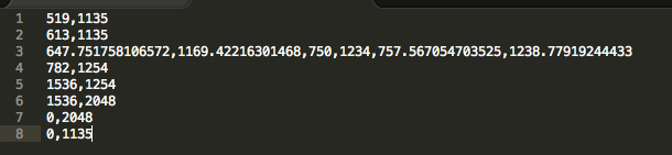
The question I have here is, consider line 3, the control points specified there, do they represent the control points for the Bezier curve between Line 2 point and Line 3 point or a Bezier curve between Line 3 point and Line 4 point?
Thanks!


 1 Correct answer

Nice link, Trevor, thanks.
So in the earlier example, this shape:
ctx.moveTo(20,20);
ctx.bezierCurveTo(20,100,200,100,200,20);
corresponds with the shape you get in InDesign with this script:
g = app.documents[0].pages[0].graphicLines.add ({strokeWeight: 0.5});
g.paths[0].entirePath =
[
[[20, 20], [20, 20], [20, 100]],
[[200, 100], [200, 20], [200, 20]],
];
The curve has two anchors. First anchor at 20,20; no handle, i.e. the incoming handle is on the anchor. The second point has no outgoing handle.
To t
... 40
Replies
40
40
Replies
40
Copy link to clipboard
Copied
I would think that the left control points go to the left (750,1234) which in your specific case is between 2 and 3 and that the right control points go to the right (757, 1238) which in your case is between 3 and 4.
Copy link to clipboard
Copied
But I believe this is a quadratic Bezier curve and there need to be two control points to represent it accurately. How would that be satisfied if what you propose is true?
Copy link to clipboard
Copied
I think it's cubic and not quadratic, I once looked into it and seem to remember that's what I found documented.
Time for some googling
Copy link to clipboard
Copied
InDesign's curves and handles essentially work the same way as in FontLab, Fontographer, Illustrator, CorelDraw, etc.
P.

Copy link to clipboard
Copied
pkahrel wrote:
InDesign's curves and handles essentially work the same way as in FontLab, Fontographer, Illustrator, CorelDraw, etc.
.. and inside Type 1 PostScript fonts! (But not TTF fonts. Now those are quadratic, not cubic.)
Copy link to clipboard
Copied
It's clearer if you present the path as an array of arrays (values rounded here):
[
[519,1135],
[613,1135],
[[647,1169],[750,1234],[757,1238]],
[782,1254],
[1536,2048]
]
The third line indicates that the anchor point is at [750,1234] and that the anchor has two handles. When you select an anchor with the direct selection tool you see any handles. The anchor point in line 3 has two handles: the incoming one ('leftDirection') is [647,1169], the outgoing one ('rightDirection') is [757, 1238]. The values are the coordinates of the handles. When you select a handle, the Transform panel shows the coordinates of the anchor, not the handle. (Only when you press a handle and you keep the mouse button down do you see the handle's coordinates, but very briefly.) But you can see a handle's coordinates in the Info panel, see the screenshot.

The selected anchor is at 186,400, the outgoing ('rightDirection') handle is at 220,400 (couldn't get the mouse pointer exactly on the spot). The path of this curve can be represented in several ways:
[
[[134, 500], [134, 457], [134, 420]],
[[150, 400], [186, 400], [220, 400]],
[[230, 420], [230, 436], [230, 457]],
]
or
[
[leftDirection = [134, 500],
anchor = [134, 457],
rightDirection = [134, 420]
],
[leftDirection = [150, 400],
anchor = [186, 400],
rightDirection = [220, 400]
],
[leftDirection = [230, 420],
anchor = [230, 436],
rightDirection = [230, 457]
],
];
Peter
Copy link to clipboard
Copied
Thanks a ton for this comprehensive explanation! 
Copy link to clipboard
Copied
I have one more question. So I understand, the Bezier between two anchor points a and b can be drawn using the leftControl of b and rightControl of a. But according to the screenshot I posted above, it is not possible as there is no other anchor point with controlPoints so how would I draw a Bezier then?
Copy link to clipboard
Copied
Let's sort out some terminology: a Bézier curve is the whole curve. What you call 'control points' are usually called 'handles'. Those handles are used to change the shape of the curve. How exactly the shape is changed when you drag a handle depends on the type of anchor: smooth, symmetrical, etc.
If you have two anchors a and b, the shape of the curve connection a and b can be changed by dragging the outgoing handle of a and/or the incoming handle of b (assuming that you started at a).
To place an anchor with handles, choose the pen tool, click somewhere, keep the mouse button down, and drag somewhere. You'll see the handles appear. If you've not worked with Bézier before it can be a bit of a challenge but it's not really very difficult. Some practice will make things clear. Look into point conversion (Object > Convert point) and the Convert Direction Tool in the Tools menu. Doodle around and draw and change lots of curves!
P.
Copy link to clipboard
Copied
I thought that every anchor point was connected by Bezier curves and using the control points I could draw a curve in HTML too. What do I do if I wish to do that?
Copy link to clipboard
Copied
> I thought that every anchor point was connected by Bezier curves . . .
Yes, you're right about that.
> . . . and using the control points I could draw a curve in HTML too. What do I do if I wish to do that?
In HTML? I haven't a clue.
Copy link to clipboard
Copied
So to draw a Bezier curve between two points we need the two points between which we wish to draw a curve and two control points. So considering I have the information supplied by InDesign, how would that translate into the the format I require, that is basically my query.
Copy link to clipboard
Copied
Not so much an indesign question but you can mess around with HTML canvas bezierCurveTo() Method and google bezier curve html5 demo
Copy link to clipboard
Copied
This is a nice link https://developer.mozilla.org/en-US/docs/Web/API/Canvas_API/Tutorial/Drawing_shapes
The below is pasted from there
Cubic Bezier curves
This example draws a heart using cubic Bézier curves.
function draw() {
var canvas = document.getElementById('canvas');
if (canvas.getContext){
var ctx = canvas.getContext('2d');
// Quadratric curves example
var path = new Path2D();
path.moveTo(75,40);
path.bezierCurveTo(75,37,70,25,50,25);
path.bezierCurveTo(20,25,20,62.5,20,62.5);
path.bezierCurveTo(20,80,40,102,75,120);
path.bezierCurveTo(110,102,130,80,130,62.5);
path.bezierCurveTo(130,62.5,130,25,100,25);
path.bezierCurveTo(85,25,75,37,75,40);
ctx.fill(path);
}
}
Copy link to clipboard
Copied
Nice link, Trevor, thanks.
So in the earlier example, this shape:
ctx.moveTo(20,20);
ctx.bezierCurveTo(20,100,200,100,200,20);
corresponds with the shape you get in InDesign with this script:
g = app.documents[0].pages[0].graphicLines.add ({strokeWeight: 0.5});
g.paths[0].entirePath =
[
[[20, 20], [20, 20], [20, 100]],
[[200, 100], [200, 20], [200, 20]],
];
The curve has two anchors. First anchor at 20,20; no handle, i.e. the incoming handle is on the anchor. The second point has no outgoing handle.
To translate InDesign's path to HTML, do a moveTo to the path's first anchor (myCurve.paths[0].pathPoints[0].anchor).
From there you can work out how to proceed.
P.

Copy link to clipboard
Copied
Hi all,
First, InDesign uses cubic Bezier curves.
And now, here is the best reference ever about dealing with Bezier curves:
@+,
Marc

Copy link to clipboard
Copied
Marc Autret wrote:
And now, here is the best reference ever about dealing with Bezier curves:
Wow! Now that is comprehensive!
I've bookmarked that page to read when I have the mental capacity to digest some of it... 
Thanks!
Harbs
Copy link to clipboard
Copied
This is exactly what I wanted! Thanks a lot!
Rishabh K
Copy link to clipboard
Copied
The easiest way to draw this stuff in HTML is using EaselJS.
Copy link to clipboard
Copied
HI Marc and all,
I made a script earlier in the year and read at least some that link then, it was a bit difficult to apply in practice in Illustrator or InDesign.
I needed to as per UI entry draw templates with arches at their ends using bezier curves. For the simple 1/4 circles rounded corners I used an approximation of something like .55 for the right handle and .45 for the left.
Below is a snippet of part of the script (it was for Illustrator but the principles are the same for ID)
const kLeft = r * 0.44771575927734444444, // constant for leftDirection handle for a 90 degree arc
      kRight = r * 0.55228508843315972222; // constant for rightDirection handle for a 90 degree arc
var c, l, arcPaths, pathPoints;

top = (top == true || top == "top") ? "top" : "bottom";

arcPaths = {
    top : { // top path starting from top right
            anchors: [[x, y], [x - r, y - r]],
            rightDirections: [[x, y], [x - r, y - kLeft]],
            leftDirections: [[x - kRight, y], [x - r, y - r]],
            pointTypes: [PointType.CORNER, PointType.CORNER]
        },

    bottom: { // bottom path starting from top left
            anchors: [[x, y], [x + r, y - r]],
            rightDirections: [[x, y], [x + kLeft, y - r]],
            leftDirections: [[x, y - kRight], [x + r, y - r]],
            pointTypes: [PointType.CORNER, PointType.CORNER]
        }
};
The above would produce the paths and handles which I pushed into arrays to produce the shapes.
That was the easy bit. The harder bit was that I needed to adds arches of a given radius and width / sagitta.
I wanted to do it mathematically but in the end took the path that I think the OP is taking of using ID or Ai as a crutch to do the math, so I got Ai to draw a circle and a correctly placed rectangle, excluded the rectangle from the circle copied the path of the resulting arc, removed the arc and added the path to the shapes entire path array.
To draw a circle one would use 4 1/4 circles that would be easy enough, to draw an ellipse presumably one would average out the handles in some form of proportion to the translation or the ellipses anchor points from the circle anchor points. I haven't experimented to get it to work.
What I wanted to do was to make a generic function for segments of ellipses, of height h and width w starting from and a and ending at b.
I know from you sin script tat you read up on the topic. Do you know how to go about it?
Regards
Trevor
Copy link to clipboard
Copied
Hi Trevor,
I didn't work specifically on ellipses (so far) but I suppose all could be done by just scaling data from basic circle path points. So the main question is about managing circles (and circle arcs) in terms of cubic Bezier curves.
As we already know a Bezier curve cannot perfectly match an exact circle but there are decent approximations (InDesign native circle routine is not very good, by the way). A good read on this issue is: Approximate a circle with cubic Bézier curves (There are also technical details in Drawing Sine Waves in InDesign, although this is a subsidiary topic.)
There are great libraries to study Bezier art in depth. For JavaScript dev I specially recommand Paper.js (many interesting snippets here). And at a higher level (C++) we have of course Inkscape's source code: https://inkscape.org/en/download/source/
Using DOM commands (Pathfinder operations etc.) remains the easier solution anyway… as long as you do not question performances.
Now, going back to your question, give us more detail on what your routine is exactly supposed to do in terms of input/output, then maybe I could bring a starting point.
@+
Marc
Copy link to clipboard
Copied
Trevor, there is a very nice PDF floating around on the web which explains in detail the differences between bezier curves and circle segments. But (looking at your magic values) perhaps you've already seen it?
(As a note to others: mathematically you can prove that you cannot draw circles - or ellipses - using bezier curves only, although you can approximate them. Technically, neither InDesign's nor Illustrator's circles are, in fact, actual circles.)
Copy link to clipboard
Copied
Hi Marc and Jongware
Thanks for your reply.
I'll get back tomorrow afternoon.
Trevor
Copy link to clipboard
Copied
Ok, the afternoon came and went.
I did see a lot of sources on the topic but didn't understand how to apply the theory and the terms used in them to practical ID, AI scripting terms.
I am using the terms circles, ellipses etc. as what the look like and what most "normal" people would call them even though I fully understand that they are approximations. I did see in one of the sources (no idea which) that a better value can be given instead of the standard .552... that is used. The numbers that I used I think I got by looking at the paths that Ai was producing. The numbers didn't produce a fixed constant a bigger "circle" produced a different number than a smaller one.
I only noticed now that I didn't need to use 2 numbers .522... and .447... as the .447... is 1 - .52222
I looked today at the Paper.js in particular the function that starts at line 4474 of the paper-core.js file. Which I shall paste below.
It helps a very lot in understanding things. Now that from this post we know the conversion from extended script to and from the html "ctx.bezierCurveTo()" it opens up the topic tremendously.
_draw: function(ctx, param, strokeMatrix) {
var style = this._style,
    hasFill = style.hasFill(),
    hasStroke = style.hasStroke(),
    dontPaint = param.dontFinish || param.clip,
    untransformed = !strokeMatrix;
if (hasFill || hasStroke || dontPaint) {
    var type = this._type,
        radius = this._radius,
        isCircle = type === 'circle';
    if (!param.dontStart)
        ctx.beginPath();
    if (untransformed && isCircle) {
        ctx.arc(0, 0, radius, 0, Math.PI * 2, true);
    } else {
        var rx = isCircle ? radius : radius.width,
            ry = isCircle ? radius : radius.height,
            size = this._size,
            width = size.width,
            height = size.height;
        if (untransformed && type === 'rectangle' && rx === 0 && ry === 0) {
            ctx.rect(-width / 2, -height / 2, width, height);
        } else {
            var x = width / 2,
                y = height / 2,
                kappa = 1 - 0.5522847498307936,
                cx = rx * kappa,
                cy = ry * kappa,
                c = [
                    -x, -y + ry,
                    -x, -y + cy,
                    -x + cx, -y,
                    -x + rx, -y,
                    x - rx, -y,
                    x - cx, -y,
                    x, -y + cy,
                    x, -y + ry,
                    x, y - ry,
                    x, y - cy,
                    x - cx, y,
                    x - rx, y,
                    -x + rx, y,
                    -x + cx, y,
                    -x, y - cy,
                    -x, y - ry
                ];
            if (strokeMatrix)
                strokeMatrix.transform(c, c, 32);
            ctx.moveTo(c[0], c[1]);
            ctx.bezierCurveTo(c[2], c[3], c[4], c[5], c[6], c[7]);
            if (x !== rx)
                ctx.lineTo(c[8], c[9]);
            ctx.bezierCurveTo(c[10], c[11], c[12], c[13], c[14], c[15]);
            if (y !== ry)
                ctx.lineTo(c[16], c[17]);
            ctx.bezierCurveTo(c[18], c[19], c[20], c[21], c[22], c[23]);
            if (x !== rx)
                ctx.lineTo(c[24], c[25]);
            ctx.bezierCurveTo(c[26], c[27], c[28], c[29], c[30], c[31]);
        }
    }
    ctx.closePath();
}
From this it should be pretty simple to parse in the jsx. With this we can draw an ellipse, or a 1/4, 1/2 and 3/4 ellipse using 1, 2, 3 or 4 bezier curves.
This is really all I need, but what I would like is to be able to start and end at any point in the ellipse.
Given H, W, and start and end angles S and E how would I calculate the black bezier curve on the right side of the screenshot?

-
- 1
- 2

Find more inspiration, events, and resources on the new Adobe Community
Explore Now
 AdChoices