- Home
- Illustrator
- Discussions
- Cavalier and military projection: Rules?
- Cavalier and military projection: Rules?
Copy link to clipboard
Copied
Hello,
I am not sure where else I can ask this question. I have seen a few great answers on these forums related to axonometric projection … I thought I'd take a shot in the dark and see if I can get help related to oblique projection rules.
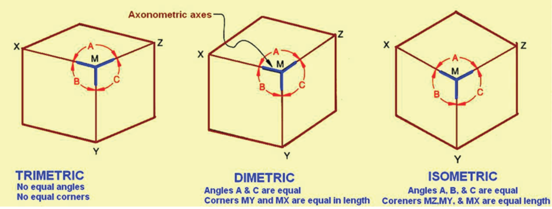
For some context, I have been scouring the web to learn the rules of axonometric and oblique projections. I have had a lot of success learning the basic "rules" of axonometric. For example, I thought this was a good guide:

Question: What are the rules of oblique cavalier and military projection?
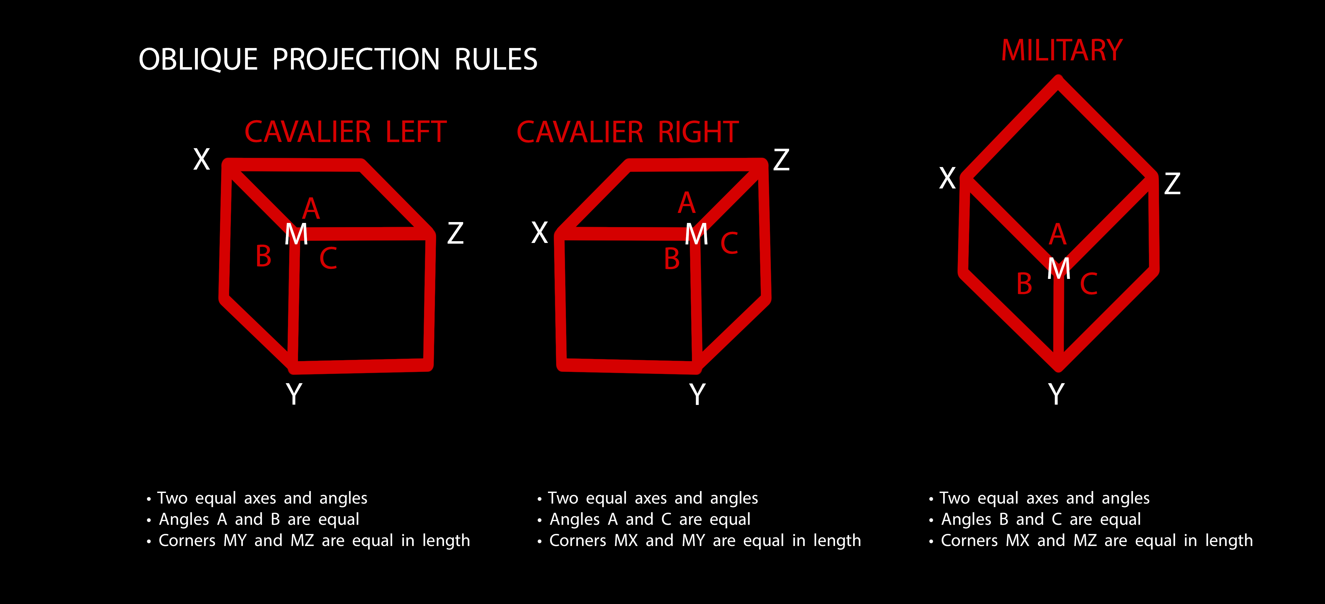
Based on what I have found on the web (which was not much in comparison to axonometric) here's what I have come up with:

Can anyone tell me if the above "rules" are correct for oblique projection?
My end goal is to create art in Illustrator using oblique projections, but before I do this, I really want to make sure I fully understand the basic concepts/rules of the projection I'll be using (cavalier left/right and military, as seen above).
I would love some help!
 1 Correct answer
micky,
Your choice of words ("rules") is a good way to address the fundamental difference between oblique methods and axonometric methods. Oblique methods are basically a set of arbitrary "rules"; a set of conventions agreed upon just for the sake of consistency. (You left out cabinet oblique, by the way.)
You can know this intuitively, because in the obliques you've mentioned, one plane of the coordinate system (one side of the cube) is shown "in the flat", as if looking directly at it. You know,
...Explore related tutorials & articles
Copy link to clipboard
Copied
Hi mickyhulse,
Here are some tutorials for you.
Create oblique projection with OPO plug-in for Adobe Illustrator - Illustrator Tips - Vectorboom
Create an Oblique Grid with Adobe Illustrator - YouTube
Hope This helps !
Regards
Srishti
Copy link to clipboard
Copied
Thanks for linkages srishtib8795206, I really appreciate the help. ![]()
Reading through/watching links now.
I did recently buy the OPO plugin. I'm looking forward to using it.
Copy link to clipboard
Copied
micky,
Your choice of words ("rules") is a good way to address the fundamental difference between oblique methods and axonometric methods. Oblique methods are basically a set of arbitrary "rules"; a set of conventions agreed upon just for the sake of consistency. (You left out cabinet oblique, by the way.)
You can know this intuitively, because in the obliques you've mentioned, one plane of the coordinate system (one side of the cube) is shown "in the flat", as if looking directly at it. You know, of course, that when actually viewing a cube in that way, you can't see the adjacent sides at all.
But axonometric is not like that at all. Axonometric methods are entirely geometry derived; it's not a set of arbitrary "rules," but a matter of geometric principles. The result of axonometric drawing is a mechanically correct orthographic projection. It's either geometrically correct, or it isn't. And the example you posted is a case-in-point, but not, I'm afraid, in the way you think:
I have had a lot of success learning the basic "rules" of axonometric. For example, I thought this was a good guide:
That is actually a very bad example, and is very misleading because it implies that all three drawings are of a cube. But as depicted, the ostensibly "dimetric" and "trimetric" drawings cannot be cubes.
It's an example of what I meant above about your use of "rules": The captions of the example state that the three isometric axes make equal angles with each other on the page, that dimetric has one unequal angle between its axes, and that trimetric uses three different axis spacings. That's true, but entirely leaves out half of the underlying principle: It's not a simple matter of arbitrarily selecting either one, two, or three angular spacings on the page. In all three methods, the measuring scale of the three axes must also be correctly proportional.
The angles and the lengths of the three axes are interdependent. For any given set of angles between the axes, there is only one set of correctly proportional scales by which to measure along the axes.
You can see this intuitively by just looking a little more closely at the supposedly "dimetric" example. The "cube" is clearly disproportionally short and squat in the vertical direction.
You can also see it in the supposedly "trimetric" example. Clearly the Z axis is viewed at a more acute angle relative to the line-of-sight than is the X axis. In other words, the X axis is clearly closer to perpendicular to your line-of-sight than is the Z. Yet the Z edges of the "cube" are longer.
This stuff "hurts the eyes" of experienced axonometric illustrators (kind of 'jumps off the page"). The errors are dead giveaways of incorrect construction, and will lead to other errors that cascade throughout the drawing of anything more elaborate than a cube.
JET
Copy link to clipboard
Copied
Wow, JET, thank you!
I am reading and re-reading your post now. I really appreciate you taking the time to respond and correct my thinking/understanding.
I'll post back if I have questions (which, I am sure I will). ![]()
Copy link to clipboard
Copied
Thanks, JET, this is an excellent summary. As illustration supervisor, I've simply forbidden oblique projections in my team because they appear amateurish -- it insults the reader by assuming they don't know the difference -- and it's really not that much effort to just do a real projection and the results are well worth it. There are a lot of good tools for this within and outside of Illustrator.