 Adobe Community
- Home
- InDesign
- Discussions
- Re: What is the direction of the curve points retu...
- Re: What is the direction of the curve points retu...

Copy link to clipboard
Copied
The entirePath() of a polygon returned these points. As clarified in a different thread, we have established that the order is leftControlPoint anchorPoint rightControlPoint if there are control points at all. Otherwise it is just the anchor point.
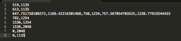
The question I have here is, consider line 3, the control points specified there, do they represent the control points for the Bezier curve between Line 2 point and Line 3 point or a Bezier curve between Line 3 point and Line 4 point?
Thanks!


 1 Correct answer

Nice link, Trevor, thanks.
So in the earlier example, this shape:
ctx.moveTo(20,20);
ctx.bezierCurveTo(20,100,200,100,200,20);
corresponds with the shape you get in InDesign with this script:
g = app.documents[0].pages[0].graphicLines.add ({strokeWeight: 0.5});
g.paths[0].entirePath =
[
[[20, 20], [20, 20], [20, 100]],
[[200, 100], [200, 20], [200, 20]],
];
The curve has two anchors. First anchor at 20,20; no handle, i.e. the incoming handle is on the anchor. The second point has no outgoing handle.
To t
... 40
Replies
40
40
Replies
40

Copy link to clipboard
Copied
Okay Trevor let's go into this!
I won't use Paper.js in my example as I have already coded a similar routine in a work-in-progress—Claquos v3—so I'll be more comfortable with my personal code.
My basic idea is, don't work with an ellipse when you can just rescale a circle (through a transformation matrix, etc.) So I'll start with a circular arc.
My main reference when I was implementing the below routine was Circular Arcs and Circles. You find there a clear explanation and method for computing the right Bézier weight for a specific arc in [0,pi/2]. Then, all we need to do is to create as many control points as needed to cover arcs over 90 degree. Here my approach is to divide the entire arc in equal sub-arcs so that I just have to deal with a single Bézier weight calculation and then apply a rotation to the successive control points. (Also, we want to manage a global rotation angle to support your S parameter, but it's not a big deal.)
// ---
// This is part of my Claquos v3 script (not released yet.)
// ---
$.hasOwnProperty('Arc')||(function(H/*OST*/,S/*ELF*/,I/*NNER*/)
{
H
= S;I.F_ROTATOR = function F(/*num[2][]&*/a)
// -------------------------------------
// A rotation utility.
{
if( !a )
{
F.FACTOR = 1e3;
F.COS = 1;
F.SIN = 0;
F.alphaDeg = 0;
F.rotate || (F.rotate = function(dAlphaDeg)
{
var a = ((F.alphaDeg += dAlphaDeg)*Math.PI)/180;
F.COS = Math.cos(a);
F.SIN = Math.sin(a);
});
return F;
}
var cos = F.COS,
sin = F.SIN,
factor = F.FACTOR,
x, y,
i = a.length;
while( i-- )
{
x = a[0];
y = a[1];
a[0] = (x*cos + y*sin)/factor;
a[1] = (y*cos - x*sin)/factor;
}
};
I.F_TANGENT_FACTOR = function(/*]0...[*/radius,/*]0,90]*/angle,/*bool=false*/ANGLE_IN_RADIANS)
// -------------------------------------
// Get the perfect Bezier weight for that angle.
{
var a = ANGLE_IN_RADIANS ? angle : ((angle * Math.PI) / 180),
x = radius * Math.cos(a),
y = radius * Math.sin(a);
return ( 4 * (Math.sqrt(radius*radius - 2*x) - (x-1)) ) / ( 3*y );
}
I.F_ARC_PATH = function(/*]0...[*/radius,/*]0,360]*/arcDeg,/*[0,360[*/rotDeg)
// -------------------------------------
// Generate the entire path.
{
var FX = I.F_ROTATOR(),
// ---
n = 2 + (arcDeg>90) + (arcDeg>180) + (arcDeg>210),
r = radius*FX.FACTOR,
// ---
alphaDeg = arcDeg / n,
kAlpha = r * I.F_TANGENT_FACTOR(r, alphaDeg/2),
// ---
path, i, z, t;
FX.rotate(rotDeg);
for( path=[], i=z=0 ; i <= n ; ++i )
{
t = path[z++] = [ null, [r,0], null ];
t[0] = i > 0 ? [r, kAlpha] : t[1].concat();
t[2] = i < n ? [r, -kAlpha] : t[1].concat();
FX(t);
FX.rotate(alphaDeg);
}
return path;
};
// -------------------------------------
// API
// -------------------------------------
S.buildPath = I.F_ARC_PATH;
})($,{toString:function(){return 'Arc'}},{});
// ---
// TEST -- assuming the ruler space is OK, in pt, etc.
// ---
var path = $.Arc.buildPath(/*radius*/100,/*arc*/270,/*rotation*/90);
app.activeWindow.activeSpread.rectangles.add({
strokeColor:'Black',
fillColor:'None',
strokeWeight:'3pt'
}).paths[0].properties = {
entirePath: path,
pathType: +PathType.OPEN_PATH,
};
Which leads to:
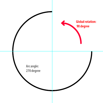
From then the only question you have to deal with is to find the parameters (i.e. radius, rotation and arc angles) that fit your final ellipse, considering some scaling factor. I guess that will be the easy part 😉
Of course I strongly suggest that you implement the scaling transformation at the path computation level (rather than scaling the circle after its creation) since every DOM command has a cost. But you already knew that.
Hope that helps.
@+,
Marc
Copy link to clipboard
Copied
Very Nice Marc!
From then the only question you have to deal with is to find the parameters (i.e. radius, rotation and arc angles) that fit your final ellipse, considering some scaling factor. I guess that will be the easy part 😉
My only doubt is just how easy the "easy part" will be.
I shall give it a go.
Thanks hope the help and time you put into it,
Trevor
Copy link to clipboard
Copied
Hi Trevor,
My only doubt is just how easy the "easy part" will be.
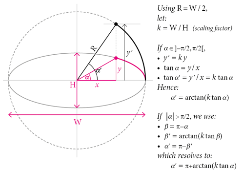
Sorry but we'll need a little bit of math here. Take R = W / 2 and k = W / H.
k is the y-scaling factor that sends the ellipse to the circle (and inversely 1/k is the y-scaling factor we shall apply to the circular arc.)
Since your parameters provide the start and end angles relative to the ellipse, the problem is to determine the corresponding angles in the circular area (that is, before stretching the circle).
Given an angle α relative to the ellipse, what is the corresponding angle α' relative to the circle? Let's solve this first in the usual trigonometric form:
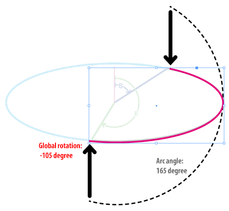
Now we can write an adapter to convert ellipse parameters into circle parameters. The code below also takes care of the angular reference frame you used in your example.
// Original Trevor's parameters
// ---
var W = 400,
    H = 144,
    S = 57,  // in degree, origin +90, reversed
    E = 212; // in degree, origin +90, reversed

// Adapter
// ---
const DEG2RAD = Math.PI/180,
      RAD2DEG = 180/Math.PI;
var   radius = W/2,
      k = W/H,
      convertEllipseToCircleAngle = function(a)
      {
        return 180*(0>Math.cos(a*=DEG2RAD)) +
            RAD2DEG*Math.atan(k*Math.tan(a));
      },
      // ---
      start = convertEllipseToCircleAngle(90-E),
      end = convertEllipseToCircleAngle(90-S),
      arc = end-start;
while( arc <= 0 ) arc+=360;


// Build the circular arc using $.Arc (see previous post.)
// ---
var path = $.Arc.buildPath(radius,arc,start);

var arc = app.activeWindow.activeSpread.rectangles.add({
    strokeColor:'Black',
    fillColor:'None',
    strokeWeight:'2pt'
    });
arc.paths[0].properties = {
    entirePath: path,
    pathType:   +PathType.OPEN_PATH,
    };

// Y-rescale by 1/k (relative to the space origin.)
// [This should be done at the coordinate level for better performance!]
// ---
arc.resize(
    CoordinateSpaces.spreadCoordinates,
    [[0,0],AnchorPoint.centerAnchor], // this refers to the ruler origin
    ResizeMethods.MULTIPLYING_CURRENT_DIMENSIONS_BY,
    [1,1/k]
    );
That's it! Here is how the script behaves for decreasing values of H:
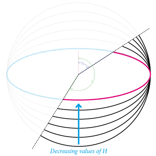
Note that the resulting angles S and E remains constant, as expected 
@+
Marc
Copy link to clipboard
Copied
These are works of art. . .
Copy link to clipboard
Copied
Excellent Marc!
Better still is.
// Original Trevor's parameters
// ---
var W = 400,
H = 144,
S = 57, // in degree, origin +90, reversed
E = 212; // in degree, origin +90, reversed
// Adapter
// ---
const DEG2RAD = Math.PI/180,
RAD2DEG = 180/Math.PI;
var radius = W/2,
k = W/H,
convertEllipseToCircleAngle = function(a)
{
return 180*(0>Math.cos(a*=DEG2RAD)) +
RAD2DEG*Math.atan(k*Math.tan(a));
},
// ---
start = convertEllipseToCircleAngle(90-E),
end = convertEllipseToCircleAngle(90-S),
arc = end-start;
while( arc <= 0 ) arc+=360;
// Build the circular arc using $.Arc (see previous post.)
// ---
var path = $.Arc.buildPath(radius,arc,start);
// Y-rescale by 1/k (relative to the space origin.)
// ---
var l = path.length,
p, ll, n, c;
for (n = 0; n < l; n++) { // loop through the circle segments
p = path
ll =p.length;
for (c = 0; c < ll; c++) { // loop through Anchor, left and right points
p
[1] /= k; // fix up the vertical scales }
}
var arc = app.activeWindow.activeSpread.rectangles.add({
strokeColor:'Black',
fillColor:'None',
strokeWeight:'2pt'
});
arc.paths[0].properties = {
entirePath: path,
pathType: +PathType.OPEN_PATH,
};
This way we avoid using the DOM resize call. This is what I need to get all the points with no DOM calls and just at the end to make the one DOM call.
The idea is to make an API to easily draw shapes in the following sort of form.
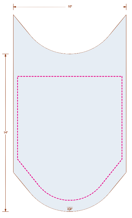
// Very Very rough numbers to make the magenta colored inner shape of the screen shot
// Aimed for Api
var path = new Shape(); // Shape is the path factory

path.start(40,500); // starting point of path
path.right(300); // or path.east (300)
path.down(300); // or path.right(300) or path.south(300)
// continue the path at a 46 degree angle for 60 points
path.right(46, 60);
// continue with an arc of radius 1000 (for ellipse could use [1000, 700] starting from 230 degrees going to 290 degrees
path.arc(500, 230, 290);
// continue the end of the arc at the current angle of the end of the arc i.e. the tangent angle of 290 by 60 points
path.continue(60);
path.up(300);
path.draw({strokeColor: 'Magenta', strokeWeight: '3pt'}); // will draw the shape with properties
The last stage of the arc function would be to allow for a rotation of the arc around the starting point.
That should be pretty basic trigonometry, I shall give it a go and hopefully post it on Sunday. (you can post it sooner if you like!)
Thanks for all you help, I'm sure this will be very useful particularly for Illustrator scripters who are doing more drawing stuff.
Regards
Trevor
Copy link to clipboard
Copied
This would go after the resize part.
// Rotate Arc from the start point by r degrees
// --
var R = 35, // Trevor's random rotation angle;
h = path[0][0][0], // horizontal start point
v = path[0][0][1]; // vertical start point
R *= DEG2RAD;
for (n = 0; n < l; n++) { // loop through the circle segments
p = path
ll =p.length;
for (c = 0; c < ll; c++) { // loop through Anchor, left and right points
Rotate(p
, [h,v], R); }
}
function Rotate(point, origin, r) {
var x = point[0],
y = point[1],
ox = origin[0],
oy = origin[1];
point[0] = (x - ox) * Math.cos(r) - (y - oy) * Math.sin(r) + ox,
point[1] = (x - ox) * Math.sin(r) + (y - oy) * Math.cos(r) + oy;
}
Copy link to clipboard
Copied
Hi All,
I think Jive's went a bit berserk and posted part of an earlier post of mine by itself, anyway I did not post it, and now I deleted it.
I did try to post another post which Jive's deleted. So here's the summary, this time typed on a text editor so it doesn't get trashed so easily.
In short; Marc has done an absolutely brilliant job in illustrating how to apply the Bezier mathematics in a practical way in InDesign and the like that makes it now easier to draw complex arcs using his functions than using the traditional path finder DOM methods. To convert the output to HTML has been illustrated in the early part of the thread opening all sorts of possibilities including producing live previews on HTML based extensions.
I have changed the structure of the functions to make it more simple for us mortals who are not yet familiar with hi unpublished Claquos v3.
I added a few functions including the ability to choose which end of the arc it the beginning.
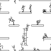
The Screenshot below is the result of the below script.
Thanks Marc!
Regards,
Trevor.
// Taken from Marc https://forums.adobe.com/message/8072664#8072664
var ArcPath, F_ROTATOR, F_TANGENT_FACTOR, EllipseArc;
var ArcPath = function(/*]0...[*/ radius,/*]0,360]*/ arcDeg ,/*[0,360[*/ rotDeg, reversePath /*[Bool]*/)
// By Marc Autret
// -------------------------------------
// Generate the entire path.
{
var FX = F_ROTATOR(),
// ---
n = 2 + (arcDeg>90) + (arcDeg>180) + (arcDeg>210),
r = radius*FX.FACTOR,
// ---
alphaDeg = arcDeg / n,
kAlpha = r * F_TANGENT_FACTOR(r, alphaDeg/2),
// ---
path, i, z, t;
FX.rotate(rotDeg);
if (!reversePath) {
for( path=[], i=z=0 ; i <= n ; ++i ) {
t = path[z++] = [ null, [r,0], null ];
t[0] = i > 0 ? [r, kAlpha] : t[1].concat();
t[2] = i < n ? [r, -kAlpha] : t[1].concat();
FX(t);
FX.rotate(alphaDeg);
}
} else { // this will make path[0][0] at the "other" end of the arc
// else part by Trevor
path=[];
i=z=n+1;
while (i--) {
t = path[--z] = [ null, [r,0], null ];
t[0] = i > 0 ? [r, -kAlpha] : t[1].concat();
t[2] = i < n ? [r, kAlpha] : t[1].concat();
FX(t);
FX.rotate(alphaDeg);
} ;
}
return path;
};
F_ROTATOR = function F(/*num[2][]&*/ a)
// By Marc Autret
// -------------------------------------
// A rotation utility.
{
if( !a )
{
F.FACTOR = 1e3;
F.COS = 1;
F.SIN = 0;
F.alphaDeg = 0;
F.rotate || (F.rotate = function(dAlphaDeg)
{
var a = ((F.alphaDeg += dAlphaDeg)*Math.PI)/180;
F.COS = Math.cos(a);
F.SIN = Math.sin(a);
});
return F;
}
var cos = F.COS,
sin = F.SIN,
factor = F.FACTOR,
x, y,
i = a.length;
while( i-- )
{
x = a[0];
y = a[1];
a[0] = (x*cos + y*sin)/factor;
a[1] = (y*cos - x*sin)/factor;
}
};
F_TANGENT_FACTOR = function (/*]0...[*/ radius , /*]0,90]*/ angle ,/*bool=false*/ ANGLE_IN_RADIANS)
// By Marc Autret
// -------------------------------------
// Get the perfect Bezier weight for that angle.
{
var a = ANGLE_IN_RADIANS ? angle : ((angle * Math.PI) / 180),
x = radius * Math.cos(a),
y = radius * Math.sin(a);
return ( 4 * (Math.sqrt(radius*radius - 2*x) - (x-1)) ) / ( 3*y );
}
// This is the main function for drawing ellipse arcs
// ---
EllipseArc = function (W, H, S, E, R, reversePath /*[Bool]*/) { // Width, Height, Start and End in degrees, origin +90, reversed Rotation in Degrees
// By Marc Autret
const DEG2RAD = Math.PI/180,
RAD2DEG = 180/Math.PI;
var radius = W/2,
k = W/H,
convertEllipseToCircleAngle = function(a)
{
return 180*(0>Math.cos(a*=DEG2RAD)) +
RAD2DEG*Math.atan(k*Math.tan(a));
},
// ---
start = convertEllipseToCircleAngle(90-E),
end = convertEllipseToCircleAngle(90-S),
arc = end-start;
while( arc <= 0 ) arc+=360;
var path = ArcPath(radius, arc, start, reversePath);
// Y-rescale by 1/k (relative to the space origin.)
// ---
var l = path.length,
p, ll, n, c;
for (n = 0; n < l; n++) { // loop through the circle segments
p = path
ll =p.length;
for (c = 0; c < ll; c++) { // loop through Anchor, left and right points
p
[1] /= k; // fix up the vertical scales }
}
if (R) {
// Rotate Arc from the start point by r degrees
// --
Rotate(path, R);
}
return path;
}
Rotate = function (path /*object or array*/, R) { // Rotates all the points in the path around the starting point of the path
// By Trevor
R *= Math.PI / 180; // Convert to radians
var h = path[0][1][0], // horizontal start point
v = path[0][1][1], // vertical start point
n, p, l, ll, c;
l = path.length;
for (n = 0; n < l; n++) { // loop through the circle segments
p = path
ll =p.length;
for (c = 0; c < ll; c++) { // loop through Anchor, left and right points
RotatePoint(p
, [h,v], R); }
}
}
RotatePoint = function (point /*[Array x,y]*/, origin /*[Array x,y]*/, r /*num degrees from +90*/) { // Rotates any given point around any other given point
// By Trevor
var x = point[0],
y = point[1],
ox = origin[0],
oy = origin[1];
point[0] = (x - ox) * Math.cos(r) - (y - oy) * Math.sin(r) + ox,
point[1] = (x - ox) * Math.sin(r) + (y - oy) * Math.cos(r) + oy;
}
MoveTo = function (path /*object or array*/, x, y) { // translates the path to start at a give point
// By Trevor
var q = path.length - 1;
var h = x - path[0][1][0], // horizontal translation from start point
v = y - path[0][1][1], // vertical translation from start point
n, p, l, ll, c;
ll = path.length;
for (n = 0; n < ll; n++) { // loop through the circle segments
p = path
l =p.length;
for (c = 0; c < l; c++) { // loop through Anchor, left and right points
p
[0] += h; p
[1] += v; }
}
}
Scale = function (path, x, y /* number X scale i.e. 1.2 for 120% */) {
// By Trevor
var n, p, l, ll, c;
ll = path.length;
for (n = 0; n < ll; n++) { // loop through the circle segments
p = path
l =p.length;
for (c = 0; c < l; c++) { // loop through Anchor, left and right points
p
[0] *= x; p
[1] *= y; }
}
}
// ---
// TEST
// ---
function drawSomething () {
// By Trevor
const DEG2RAD = Math.PI/180;
var n, path, c,
doc = app.documents.add({
viewPreferences: {horizontalMeasurementUnits: 'pt', verticalMeasurementUnits: 'pt'},
documentPreferences: {pagesPerDocument: 1, pageHeight: '1900pt', pageWidth: '1150pt'}
});
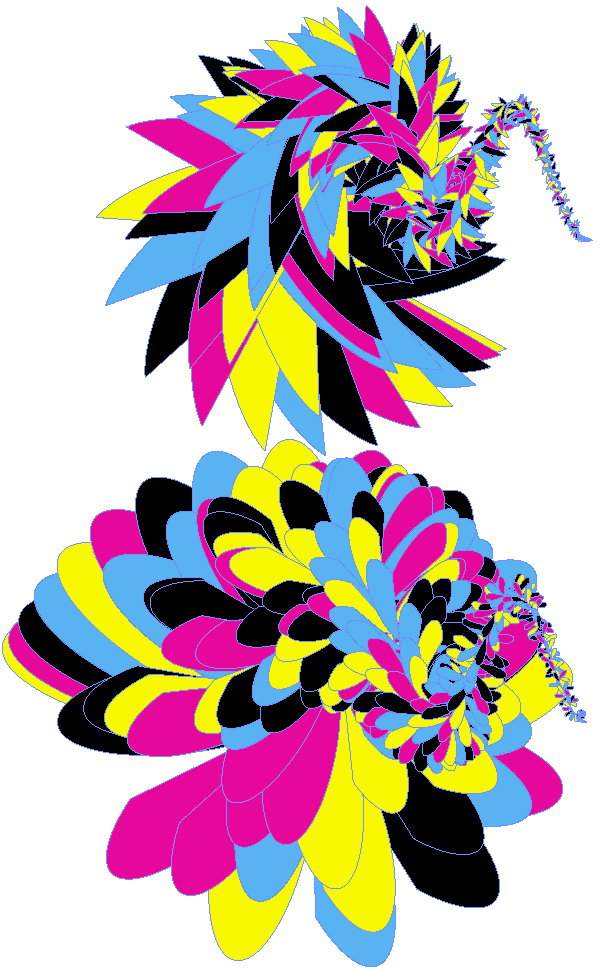
cmyk = ['Cyan', 'Yellow', 'Magenta', 'Black'];
for (c = 0; c < 2; c++) {
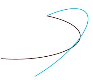
path = EllipseArc(200, 70, 100, 300, 10, c % 2 /* Boolean to reverse starting point of path */);
for (n = 0; n < 360; n++) { // change to 15 to get a better idea of what the path reversing does
// Face and Trunk
Scale(path, .99, .99);
Rotate(path, n * 2);
MoveTo (path, 200 + .5 * n, 150 + ((c) * 300) + 40 * Math.cos (n * 2 * DEG2RAD));
doc.spreads[0].graphicLines.add({
strokeColor: cmyk[n % 4],
fillColor: cmyk[(n + 1) % 4],
fillColor: cmyk[(n + 1) % 4],
strokeWeight:'.5pt',
name: "shape"
}).paths[0].properties = {
entirePath: path,
pathType: +PathType.CLOSED_PATH,
};
}
}
}
app.doScript (drawSomething, ScriptLanguage.JAVASCRIPT, undefined, UndoModes.FAST_ENTIRE_SCRIPT);
Copy link to clipboard
Copied
Hi Marc
I am doing some work on this now and was wondering why you have a factor F.FACTOR = 1e3 and why you set it to 1000?
You are multiplying the radius by the factor and then you divide by the factor so any non 0 number will produce the same result.
If it wasn't you I wouldn't ask the question but as it is you I'm sure you have good reason!
Regards
Trevor
Copy link to clipboard
Copied
Hi Trevor,
Good question. My answer will be disappointing, I'm afraid. My original purpose was all about increasing the precision of the final coordinates, considering the fact that IEEE754 arithmetic (floating-point numbers) is an approximation of real number arithmetic, especially when additive operations are involved. My reasoning was as follows: we know IEEE754 is just a finite set of numbers (an infinite set of real numbers can't be described with that system). Then I was supposing that adding/subtracting high numbers rather than small numbers was a way of reducing rounding errors, because if the error density is the same at any scale then finally dividing by some factor will perhaps reduce the rounding error by that factor. But to be honest there are many points in my reasoning which I'm not sure at all. I made assumptions about error density which in fact I can't prove based on the mantissa|exponent representation of floating-point numbers. Also, I'm not sure that multiplying (first) and dividing (last) does not introduce errors of the same amount that those I want to reduce (however, it is known that IEEE754 multiplication is safer than addition, so…) Finally, that 1e3 factor is purely empiric and arbitrary. Maybe a 2^n factor would be much more convenient. Etc.
Reconsidering my code after several months, I don't feel it that good and exemplary. The logic is OK but the implementation is highly questionable, indeed.
@+
Marc
Copy link to clipboard
Copied
Hi Marc,
Thanks for the detailed answer.
I think in truth that the even if one could get perfect coordinates the accuracy margin would be at a guess a 0.0000001 difference at most, this difference in our case is going to be irreverent as a 'perfect' bezier circle has an inaccuracy of about .02% of a true perfect circle at the max deviating points. So whether the accuracy is .02% or .0200001% is not important. In any case we'll never be able to see the difference even on the highest resolution printers.
The fact off the matter is that your code shows how to apply the bezier maths in a practical form and is a huge help to me.
I would like to improve on my implementation of the ellipse and rotation parts which I feel should be compressed into a single loop and not 1st draw a circle arc 2nd scale to ellipse and 3rd rotate to desired angle 4th translate the object to the desired coordinates.
Perhaps I am guilty of trying to make scripts that takes 2 seconds to execute take 1.999 seconds. Either way making the compressed form would be an interesting mathematical challenge.
Regards and thanks again,
Trevor
Copy link to clipboard
Copied
You are definitely not guilty, since scaling and translation calculations are easy to prepend. That will remove two DOM commands and undoubtedly speed up the script in a noticeable way. Especially if it has to generate a bunch of ellipses.
Have fun!
@+
Marc
Copy link to clipboard
Copied
I think in the nearly a year since the scripts were posted you forgot that my version only calls the DOM command once after all the calculations have been made.

Copy link to clipboard
Copied
Hi colleagues,
this is a very interesting discussion.
Recently I did some studies on the precission that the Pathfinder tools are doing.
I found that e.g. Adobe Illustrator is more precise than InDesign and searching for a way to do more accurate operations with the Pathfinder tools. Maybe by scaling the objects first before applying a Pathfinder action. I don't know, if this is the right place to discuss this here or maybe it's better to open another thread.
I'm bussy right now, but can come back this evening with some samples, that show a few things.
Also related is the maximum zoom percentage one can zoom in and out with InDesign. Way better is the current Illustrator in this regards…
Uwe
Copy link to clipboard
Copied
Hi Uwe,
1) Interesting, but the whole point of the exercise here is to not use any pathfinder tools. See 29 above.
2) The API I am working on is basically for Illustrator. (Actually a form of Illustrator server  ) . As the API is so removed from DOM operations I would like it to work also on InDesign but it's a little bit complicated to cover them both as the vertical positions of the 2 applications are annoyingly opposite!
Regards
Trevor
Copy link to clipboard
Copied
I wonder if the precision difference is because due to the bounding box that Illustrator draws is around the path points where as InDesign wraps the line thickness of the path in the bounding box?
Copy link to clipboard
Copied
Hi Marc and all.
After second thoughts I think the accuracy issue is significant.
Although visibly one wouldn't be able to spot the difference I have scripts fetch the positions of the pathItems and marks them them up so it's no good to show 1500.0001 instead of 1500. For multi-ups the problem multiplies.
I decided to use a bit of trigonometry and were possible keep the anchor points at 90 degree points (0, 90, 180 and 270).
When not or in order to save a superfluous point I determine the anchor points by trigonometry.
I think this is the methodology that Adobe and others use.
I made a getKappa function to calculate the control points.
I needed this for Illustrator and the math was really tough for me. It took a log of guesses until I got it!
Higher numbers in InDesign are lower on the page, in Illustrator they are lower. Once I figured out the getKappa function for Illustrator the InDesign part was comparatively simple.
I tried to keep the script readable  it works for both InDesign and Illustrator.
I did make a quicker more efficient version of the arc function but the below one is quick enough and more simple so I have gone for that
I hope some people find it useful and think I shall make an extension out of it.
Enjoy
Trevor
/****************************************************************************************************
** **
** InDistrator Arc.js - Version 1 - 24 Aug 2016 **
** **
** Draws Arcs maintaining the anchors were possible at the 90 degree points (0, 90, 180, 270) **
** This provides the desired accuracy and produces 'tidy' curves **
** Works on both Illustrator and InDesign 🙂 **
** https://forums.adobe.com/message/8917563#8917563 **
** By Trevor http://www.creative-scripts.com **
** Hope to have a few posts out within the next 6 months **
** Credit to Marc Autret of http://indiscripts.com/ for opening up the topic **
****************************************************************************************************/
/* jshint undef:true, unused:true, esversion:6 */
/* globals app, MeasurementUnits, StrokeAlignment, DocumentPreset, RulerUnits */
/**
* [arc description]
* Calculates the path of an arc centered at [0,0] with a radius of 1
* The circle and ellipse functions should be used to scale and position the arc
* @param {Number} start Start angle in degrees
* @param {Number} end End angle in degrees
* @return {Array} The path of the arc
*/
function arc(start, end) {
// By Trevor
var angle, currentEnd, currentSegment, currentStart, l, segmentPath, circlePath = [];
while (start < 0) { start += 360; }
while (end < 0) { end += 360; }
start %= 360;
end %= 360;
if (end <= start) { end += 360; }
// If the arcs less than 90 degrees we can take a short cut.
// This will also remove the superfluous point
angle = end - start;
if (angle <= 90) {
return getKappa(angle, start);
}
currentStart = start;
currentSegment = Math.ceil(currentStart / 90);
do {
currentEnd = Math.min(end, currentSegment * 90);
angle = currentEnd - currentStart;
l = circlePath.length;
segmentPath = getKappa(angle, currentStart);
if (!l) {
circlePath = (segmentPath);
} else {
circlePath[l - 1][2] = [segmentPath[0][2][0], segmentPath[0][2][1]];
circlePath
= [ [segmentPath[1][0][0], segmentPath[1][0][1]],
[segmentPath[1][1][0], segmentPath[1][1][1]],
[segmentPath[1][2][0], segmentPath[1][2][1]]
];
}
currentStart = currentEnd;
currentSegment++;
} while (currentStart < end);
return circlePath;
} // end of Arc
/**
* [getKappa description]
* Used for getting the kappa values of the bezier control point
* This function was made by Trevor of http://creative-scripts.com
* After a VERY lot of effort
* @param {Number} angle The total angle in degrees of the arc
* @param {Number} start The starting angle of the arc 0 is North 90 is east
* @return {Array} The path of the segment
*/
function getKappa(angle, start) {
var a, am, sin, cos, f, af, c1, c2, entirePath, p1, p2;
a = ((angle * Math.PI) / 180);
if (app.name === 'Adobe InDesign') {
p1 = [1, 0];
start -= 90;
af = a / 4;
cos = Math.cos(a);
sin = Math.sin(a);
f = 4 * Math.tan(af) / 3;
p2 = [cos, sin];
c1 = [1, f];
c2 = [cos + f * sin, sin - f * cos];
} else if (app.name === 'Adobe Illustrator') {
p1 = [0, 1];
am = (((90 - angle) * Math.PI) / 180);
af = a / 4;
cos = Math.cos(am);
sin = Math.sin(am);
f = 4 * Math.tan(af) / 3;
p2 = [cos, sin];
c1 = [f, 1];
c2 = [cos - f * sin, sin + f * cos];
}
entirePath = [
[p1.slice(), p1.slice(), c1],
[c2, p2.slice(), p2.slice()]
];
if (start) {
rotate(entirePath, start);
}
return entirePath;
} // end of getKappa
/**
* [circle description]
* @param {Number} radius radius
* @param {Number} start Start angle in degrees
* @param {Number} end End angle in degrees
* @param {Number} x x location of the 1st point
* @param {Number} y y location of the 1st point
* @return {Array} The path
* To rotate use the rotate function on the path
*/
function circle(radius, start, end, x, y) {
return ellipse(radius, radius, start, end, x, y);
}
/**
* [ellipse description]
* Create an ellipse arc
* One can altered to have the x, y coordinate refer to a standard anchor point like center, top_right
* @param {Number} radiusX Horizontal radius
* @param {Number} radiusY Vertical radius
* @param {Number} start Start angle in degrees
* @param {Number} end End angle in degrees
* @param {Number} x x location of the 1st point
* @param {Number} y y location of the 1st point
* @return {Array} The path
* To rotate use the rotate function on the path
*/
function ellipse(radiusX, radiusY, start, end, x, y) {
// By Trevor
if (start === undefined) { start = 0; }
if (end === undefined) { end = 360; }
var path = arc(start, end);
var n, points, l, ll, c;
if (radiusX === undefined) radiusX = 1;
if (radiusY === undefined) radiusY = radiusX;
if (x === undefined) x = 0;
if (y === undefined) y = 0;
x -= path[0][1][0] * radiusX;
y -= path[0][1][1] * radiusY;
ll = path.length;
for (n = 0; n < ll; n++) { // loop through the circle segments
points = path
; l = points.length;
for (c = 0; c < l; c++) { // loop through Anchor, left and right points
points
[0] = points [0] * radiusX + x; points
[1] = points [1] * radiusY + y; }
}
return path;
}
/**
* [rotate description]
* @param {Number} path The path in entirePath form
* @param {Number} angle In degrees
* @return {Array} The rotated path
*/
function rotate(path /*array*/ , angle) { // Rotates all the points in the path around the starting point of the path
// By Trevor
var polarity = (app.name === 'Adobe InDesign') ? 1 : -1;
angle *= polarity * Math.PI / 180; // Convert to radians and switch angle to clockwise
var n, p, l, ll, c;
l = path.length;
for (n = 0; n < l; n++) { // loop through the circle segments
p = path
; ll = p.length;
for (c = 0; c < ll; c++) { // loop through Anchor, left and right points
rotatePoint(p
, [0, 0], angle); }
}
} // end of rotate
/*[Array x,y]*/
/*[Array x,y]*/
/*num degrees from +90*/
/**
* [rotatePoint description]
* changes the points give to the desired rotated coordinates
* @param {Array} point [x, y] The point to be rotated
* @param {Array} origin [x, y] The point to rotate around
* @param {[type]} r Angle in RADIANS
* @return {undefined} [description]
*/
function rotatePoint(point, origin, r) { // Rotates any given point around any other given point
// By Trevor
var x, y, ox, oy;
x = point[0];
y = point[1];
ox = origin[0];
oy = origin[1];
point[0] = roundErrors((x - ox) * Math.cos(r) - (y - oy) * Math.sin(r) + ox);
point[1] = roundErrors((x - ox) * Math.sin(r) + (y - oy) * Math.cos(r) + oy);
} // end of rotatePoint
/**
* [draw description]
* for InDesign and Illustrator
* draws the path
* If an DOM item is provided the path will be given to that DOM item.
* If the item is not provided the path will be applied to the selected item.
* If no item is selected then a new DOM item will be created
* @param {Array} path In entierPath form
* @param {DOM} item [Optional]
* @param {Object} properties [Optional] The path properties
* @return {DOM} The Item
*/
function draw(path, item, properties) {
// By Trevor
// deal with InDesign 1st, dead simple 🙂
// Sorry no checking for invalid DOM objects so try not to be a twit
if (app.name === 'Adobe InDesign') {
if (item === undefined) {
if (!app.properties.activeDocument) { app.documents.add(); }
item = (app.selection[0]) ? app.selection[0] : app.activeWindow.activeSpread.graphicLines.add();
}
properties = properties || {};
properties.entirePath = path;
item.paths[0].properties = properties;
return item;
}
// End of InDesign
// If it's not InDesign then it better be Illustrator
var doc, l, p, c, t, point, anchors, rights, lefts, leftDirection, rightDirection, prop, entirePath;
doc = (app.documents.length) ? app.activeDocument : app.documents.add();
if (item === undefined) {
item = (app.selection[0]) ? app.selection[0] : doc.pathItems.add();
}
anchors = [];
lefts = [];
rights = [];
entirePath = path;
l = entirePath.length;
if (!l) return item; // if there's no path we ain't going to draw it.
for (p = 0; p < l; p++) {
point = entirePath
;
t = point.length;
// check if the point contains anchor, left-directions, and right-directions
if (point.length === 3) {
// anchor, left and right provided
anchors.push(point[1]);
lefts.push(point[0]);
rights.push(point[2]);
} else {
// no left and rights provided just the anchor
anchors.push(point);
lefts.push(undefined);
rights.push(undefined);
} // end of if
} // end of for
// we should now have 3 equal length array
// the anchors array is any array of arrays
// the lefts and rights will be an array that can be a mixture of arrays and undefined
// 1st set the anchors of the item
item.setEntirePath(anchors);
// then set the lefts and rights
for (c = 0; c < l; c++) {
leftDirection = lefts
; rightDirection = rights
; if (leftDirection) { item.pathPoints
.leftDirection = leftDirection; } if (rightDirection) { item.pathPoints
.rightDirection = rightDirection; } }
// Set properties if provided
if (properties) {
for (prop in properties) {
item[prop] = properties[prop];
}
}
return item;
} // end of draw
/**
* [roundErrors description]
* Rounds JS errors like 0.9999999999999 or 6.2e-16 to 1 or 0
* @param {Number} n The number to be rounded
* @return {Number} The rounded number
*/
function roundErrors(n, acurracy) {
// By Trevor
const VERY_LITTLE_BIT = 1e-12;
var fraction;
if (!acurracy) { acurracy = VERY_LITTLE_BIT; }
fraction = Math.abs(n - ~~n);
fraction += acurracy;
acurracy *= 2;
return ((fraction < acurracy) || (fraction > 1)) ? Math.round(n) : n;
} // end of roundErrors
/**************************************************************************************
** **
** Demo can be run on Illustrator and InDesign **
** **
**************************************************************************************/
if (app.name === 'Adobe InDesign') {
var doc, YELLOW, BLACK, NONE, PAPER, happy, shape, properties;
doc = app.documents.add({
documentPreferences: { pagesPerDocument: 1, pageHeight: '800pt', pageWidth: '800pt' },
viewPreferences: { horizontalMeasurementUnits: MeasurementUnits.POINTS, verticalMeasurementUnits: MeasurementUnits.POINTS }
});
// doc = app.activeDocument;
YELLOW = doc.colors.itemByName('Yellow');
BLACK = doc.colors.itemByName('Black');
NONE = doc.swatches.itemByName('None');
PAPER = doc.swatches.itemByName('Paper');
properties = { strokeAlignment: StrokeAlignment.INSIDE_ALIGNMENT, strokeWeight: '5pt' };
shape = draw(circle(300, 0, 360, 400, 100));
shape = draw(circle(300, 350, 30, 400, 100));
properties.fillColor = YELLOW;
properties.strokeColor = BLACK;
shape.properties = properties;
shape = draw(circle(50, 0, 360, 250, 220));
properties.fillColor = PAPER;
shape.properties = properties;
shape = draw(circle(50, 0, 360, 550, 220));
shape.properties = properties;
properties.fillColor = BLACK;
shape = draw(circle(50, 0, 360, 400, 350));
shape.properties = properties;
shape = draw(ellipse(30, 40, 260, 95, 220, 285));
properties.strokeWeight = 0;
shape.properties = properties;
shape = draw(ellipse(30, 35, 0, 360, 550, 235));
shape.properties = properties;
shape = draw(ellipse(250, 100, 100, 260, 646, 480));
happy = doc.dashedStrokeStyles.itemByName('Happy').isValid ? doc.dashedStrokeStyles.itemByName('Happy') : doc.dashedStrokeStyles.add({ name: 'Happy' });
properties.fillColor = NONE;
properties.strokeType = 'Happy';
properties.strokeWeight = '20pt';
shape.properties = properties;
} else if (app.name === 'Adobe Illustrator') {
var doc, templateDocPreset;
templateDocPreset = new DocumentPreset;
templateDocPreset.width = 800;
templateDocPreset.height = 800;
templateDocPreset.units = RulerUnits.Points;
templateDocPreset.title = 'Happy';
doc = app.documents.addDocument("Print", templateDocPreset);
// doc = app.activeDocument;
doc.defaultStrokeWidth = 8;
doc.defaultStroked = true;
doc.pageOrigin = [0, 800];
doc.rulerOrigin = [0, 800];
shape = draw(circle(300, 0, 360, 400, -100));
shape = draw(circle(50, 0, 360, 250, -220));
shape = draw(circle(50, 0, 360, 550, -220));
shape = draw(circle(50, 0, 360, 400, -350));
shape = draw(ellipse(30, 40, 260, 95, 220, -285));
shape = draw(ellipse(30, 35, 0, 360, 550, -235));
shape = draw(ellipse(250, 100, 100, 260, 646, -480));
}
-
- 1
- 2

 AdChoices