Copy link to clipboard
Copied
hi there,
i'm facing another problem with graphicLines.
Below scripts was run in 2 different templates of the same page size, margins, columns and zero origins.
app.activeDocument.viewPreferences.rulerOrigin = RulerOrigin.SPINE_ORIGIN;
myLine=app.activeDocument.graphicLines.add();
myLine.geometricBounds = ['200mm', '0mm', '200mm','300mm'];
myLine.strokeWeight ="8pt";
in the first template the Y was exactly 200mm, but in the 2nd template Y was 201.411mm
i've checked the margins, origin etc all are the same (even the " 9squares" all are the same..) the Y in fact is phyically 'shifted' in the 2nd template
please advise..
thanks much.
Hi eboda_snaf,
the following snippet should work for both specific templates.
Note: See my /* and more */ comment in the code.
A hint, that there are several other property/value pairs that can influence the creation of the object.
Or objects, that will be derived from the graphic lines in a later process.
Maybe you like to add some path points to create a polygon out of a duplicate, then it will be important how the fill color is defined, etc.pp.
...var doc = app.documents[0];
var rulerOrigin = doc.viewP
Copy link to clipboard
Copied
Cannot tell why this happens to you.
But I would not add a graphic line without giving the entire path and doing as many definitions as possible while adding:
// position of path points 1 and 2 defined in array [ [x,y],[x,y] ]
var entirePath = [ [0,200],[300,200] ];
var doc = app.documents[0];
// Do properties while adding:
var gL = doc.spreads[0].graphicLines.add
(
{
strokeWeight : "8pt" ,
strokeColor : doc.colors.itemByName("Magenta")
/* … */
}
);
gL.paths[0].entirePath = entirePath;
Regards,
Uwe
Copy link to clipboard
Copied
eboda_snaf wrote:
… i've checked the margins, origin etc all are the same (even the " 9squares" all are the same..) the Y in fact is phyically 'shifted' in the 2nd template
Different preferences for setting the caps of the graphic line perhaps?
( just an assumption, not tested )
Check endCap and endJoin values of:
app.pageItemDefaults
app.documents[0].pageItemDefaults
Regards,
Uwe
Copy link to clipboard
Copied
Uwe, what is the benefit of using pathPoints instead of geometricBounds?
Thanks
Kai
Copy link to clipboard
Copied
Hi Kai!
More "accurate" values perhaps. ?!
At least I can see a difference between:
app.activeDocument.viewPreferences.rulerOrigin = RulerOrigin.SPINE_ORIGIN;
myLine=app.activeDocument.graphicLines.add();
myLine.geometricBounds = ['200mm', '0mm', '200mm','300mm'];
myLine.strokeWeight ="8pt";alert( myLine.paths[0].entirePath );
// Result with my open document A4 landscape:
// -5.01327374675182e-13,200,299.999999999998,200
and this:
app.activeDocument.viewPreferences.rulerOrigin = RulerOrigin.SPINE_ORIGIN;
var entirePath = [ [0,200],[300,200] ];
var doc = app.documents[0];
var gL = doc.spreads[0].graphicLines.add
(
{
strokeWeight : "8pt"
// strokeColor : doc.colors.itemByName("Magenta")
/* … */
}
);
gL.paths[0].entirePath = entirePath;
alert(gL.paths[0].entirePath);
// Result with my open document A4 landscape:
// 0,200,300,200
when working with the same active document.
Regards,
Uwe
// EDITING: Removed a stray comma in the property definition of the method add().
Copy link to clipboard
Copied
Even if you are using geometricBounds with the add() method there is a difference:
app.activeDocument.viewPreferences.rulerOrigin = RulerOrigin.SPINE_ORIGIN;
var gLOne =app.activeDocument.graphicLines.add
(
{
strokeWeight : "8pt" ,
geometricBounds : [200,0,200,300]
}
);
$.writeln("gLOne: "+gLOne.paths[0].entirePath );
var entirePath = [[0,200],[300,200]];
var gLTwo = app.activeDocument.graphicLines.add
(
{
strokeWeight : "8pt"
}
);
gLTwo.paths[0].entirePath = entirePath;
$.writeln("gLTwo: "+gLTwo.paths[0].entirePath );
/*
Results:
gLOne: -5.01327374675182e-13,200,299.999999999998,200
gLTwo: 0,200,300,200
*/
Regards,
Uwe
Copy link to clipboard
Copied
Thanks Uwe for these interesting tests.
My guess is that setting entirePath is always safer than setting geometricBounds, for the former is quite equivalent to explicitly writing pathPoint coordinates, while changing bounds is very similar to reframing, an operation which indirectly impacts coordinates after additional calculations. In InDesign coordinate spaces each new calculation has a cost in terms of floating point arithmetic so we gradually lose precision. Also, we shouldn't forget that measurement units are internally converted into PostScript points, that all attributes in transformation matrices are stored in double-precision floating-point encoding (IEEE-754, 64bits), that the ruler origin coordinates relative to the pasteboard space might involve values—fraction of the spread width, etc—that have no exact representation as IEEE754 numbers, and so on. Therefore we must remember, among other things, that setting gBounds to [T,L,B,R] does not necessarily result in gBounds[0]==T && gBounds[1]==L && etc. Path points coordinates (or entirePath) are likely more reliable in this respect, although they still lead to unit-to-point conversion behind the scene.
@+
Marc
Copy link to clipboard
Copied
eboda_snaf wrote:
… in the first template the Y was exactly 200mm, but in the 2nd template Y was 201.411mmi've checked the margins, origin etc all are the same (even the " 9squares" all are the same..) the Y in fact is phyically 'shifted' in the 2nd template
Hi Marc,
but my tests would not explain the 1.411 mm shift the OP is seeing with his template.
I suspect a corruption of the InDesign document.
Maybe it would help to export the template to IDML and work on with the opened IDML file?
Without having access to the template document it's hard to suggest anything.
Regards,
Uwe
Copy link to clipboard
Copied
Hi Uwe,
Laubender wrote:
(…) but my tests would not explain the 1.411 mm shift the OP is seeing with his template.
Indeed!
I only commented your tests. So far, I have no answer to the original question 😞
@+
Marc
Copy link to clipboard
Copied
Could it be snapping to a grid?
How about a screenshot of the whole screen for both documents?
Copy link to clipboard
Copied
first of all i would like to thank all for sharing and contributing..
hi Uwe,
i've tried your method but still it doesnt solve the mentioned 'shifted' problem.
i've wanted to attach the indd files initally but could not find any attachment options here.
using below script for the 2 indd files, one gives me perfect 50mm as Y, the other gives 48.589mm.
app.activeDocument.viewPreferences.rulerOrigin = RulerOrigin.SPINE_ORIGIN;
var entirePath = [ [0,50],[100,50] ];
var doc = app.documents[0];
var gL = doc.spreads[0].graphicLines.add
(
{
strokeWeight : "8pt" ,
// strokeColor : doc.colors.itemByName("Magenta")
/* … */
}
);
gL.paths[0].entirePath = entirePath;
alert(gL.paths[0].entirePath);
i'm sharing the 2 indd files below..
https://drive.google.com/file/d/0ByiCjPKNPsxzSVlTa1ZJemRhLUk/view?usp=sharing
https://drive.google.com/file/d/0ByiCjPKNPsxzZDVCckY4TmVRS1k/view?usp=sharing
Copy link to clipboard
Copied
one thing i find it wierd is that this shift problem only happens to graphicline.
i've added a textframe as well, the resulting coordinates are exactly the same for both templates.
That's why i don't think problem lies with the templates. i really dono, could i be missing something for the graphicline?
var myTextFrame = app.activeDocument.textFrames.add({
strokeColor:"Black",
fillColor:"None",
strokeWeight:"1pt"
});
myTextFrame.geometricBounds = [20,40,60,80];
Copy link to clipboard
Copied
hi guys
i think i found the 'problem'...
solution to this is to set StrokeAlignment.INSIDE_ALIGNMENT
Thanks much for everyone. i've learned new things from you guys.
Copy link to clipboard
Copied
eboda_snaf wrote:
…solution to this is to set StrokeAlignment.INSIDE_ALIGNMENT
…
No.
Solution is to give all intended parameters if you add a new graphic line.
You simply left out strokeAlignment and other properties as well.
And then the document ( or sometimes the app ) will decide what will happen.
The missing ones will be added automatically reflecting the state of the document ( or the app ) in the moment you are executing the script.
It is simply not enough to define some of the properties and hope for the best for all others not defined.
Regards,
Uwe
Copy link to clipboard
Copied
Hi eboda_snaf,
the following snippet should work for both specific templates.
Note: See my /* and more */ comment in the code.
A hint, that there are several other property/value pairs that can influence the creation of the object.
Or objects, that will be derived from the graphic lines in a later process.
Maybe you like to add some path points to create a polygon out of a duplicate, then it will be important how the fill color is defined, etc.pp.
var doc = app.documents[0];
var rulerOrigin = doc.viewPreferences.rulerOrigin;
doc.viewPreferences.rulerOrigin = RulerOrigin.SPINE_ORIGIN;
var geoBounds = [10,0,10,50];
var entirePath = [ [0,10] , [50,10] ];
var mutualProperties =
{
strokeWeight : "8pt" ,
strokeTint : 100 ,
strokeType : "$ID/Solid" ,
strokeAlignment : StrokeAlignment.CENTER_ALIGNMENT ,
endCap : EndCap.BUTT_END_CAP ,
endJoin : EndJoin.MITER_END_JOIN ,
leftLineEnd : ArrowHead.NONE ,
rightLineEnd : ArrowHead.NONE
/* and more */
}
var gL1 = doc.spreads[0].graphicLines.add
(
{
geometricBounds : geoBounds ,
strokeColor : doc.colors.itemByName("Magenta")
}
);
var gL2 = doc.spreads[0].graphicLines.add
(
{
strokeColor : doc.colors.itemByName("Cyan")
}
);
// Assigning mutual properties:
gL1.properties = mutualProperties;
gL2.properties = mutualProperties;
// Working with path points:
gL2.paths[0].entirePath = entirePath;
doc.viewPreferences.rulerOrigin = rulerOrigin;
What's the difference in the templates?
See this here:
Template 1:
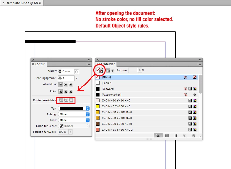
Template 2:
Regards,
Uwe
Copy link to clipboard
Copied
agreed. thank you so much