 Adobe Community
- Home
- After Effects
- Discussions
- How to rotate a binding piece in gear animation?
- How to rotate a binding piece in gear animation?

Copy link to clipboard
Copied
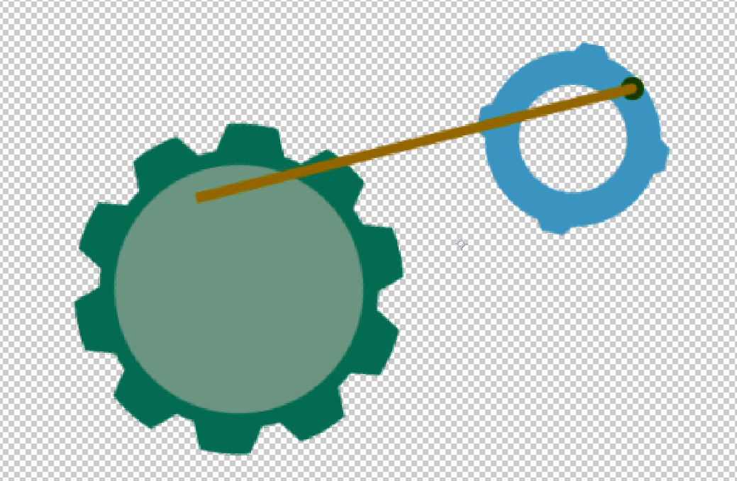
I have to create kind of a motor animation.
We have 2 rotating gears and a binding piece. My problem is that I do not know how to rotate both ends of the binding piece accordingly.
Maybe someone has an idea here?


 1 Correct answer

Here's a project created with a simple expression that takes the size an ellipse in two different shape layers and comes up with a ratio so that they turn in sync as if gears were meshing. There is also an expression that sets the number of teeth if you use a stroke with gaps and dashes to simulate gears. Feel free to play with it: Dropbox - Funky Gears.aep
To the comp that was created entirely with some animation presets that I have in my collection, I added an additional ellipse in the center o
... 8
Replies
8
8
Replies
8
Copy link to clipboard
Copied
Let's clarify exactly what you want to happen.
If the connecting rod is a fixed length and the small gear on the right rotates continuously the large gear will move back and forth and never rotate completely.
If the connecting rod is a fixed length and the large gear on the left rotates continuously the small gear will have to physically move because it cannot be driven by the connecting rod, maintain it's position and rotate continuously.
The only other option is that the attach point of the connecting rod on each gear is fixed to each gear and as they both continuously rotate the length of the connecting rod changes. That will produce a very odd looking motion.
All solutions involve expressions and parenting or just expressions. No solution is as simple as just running a script. Let us know which scenario you want and somebody can come up with a solution.

Copy link to clipboard
Copied
You can calculate the rotation angle for the "binding piece" using trigonometry but when everything is parented together it can get messy. Given what your shapes look like, I would cheat and use the Beam effect:
- Create two Null layers, placed where the ends of the "binding piece" attached to the gears, and parent those layers to the respective gears so they rotate along with them.
- Create a new Solid and apply the Beam effect.
- Set the Beam up as required : length 100%, start/end thickness equal, softness 0.0, inside/outside color the same.
- Alt-click the Starting Point and enter an expression that will tie it to the true position of the first Null layer...
N = thisComp.layer("Null 1");
N.toWorld(N.anchorPoint)
- Do the same for Beam > Ending Point, but with the other point (e.g "Null 2").
No matter how all the shape layers are parented or animated, the beam will always join the two nulls, and there's no trigonometry involved 
Copy link to clipboard
Copied
Dave's solution will cause the connecting rod to change length - so you already have a start on one scenario.
Copy link to clipboard
Copied
https://forums.adobe.com/people/Rick+Gerard wrote
Dave's solution will cause the connecting rod to change length - so you already have a start on one scenario.
Yes, but if jarkor moves the crank attachment point a tiny bit closer to the axis of the larger wheel, it would be a fixed length.
Nobody is going to freeze-frame the video to check if it's mechanically plausible, a small change in the length will be much less obvious than if the connection points shift position on their wheels - which is what inevitably happens if you use trigonometry to devise a "look at" constraint and haven't scaled every shape perfectly.
For completeness it's worth saying that AE does have a "LookAt" function, but it only works in 3D.... because nobody in Adobe considered that people making videos might want to animate in just two dimensions. 

Copy link to clipboard
Copied
For this kind of stuff nothing can compete with Newton
Here's just one example
Steve
Copy link to clipboard
Copied
DigitalSpatula wrote
For this kind of stuff nothing can compete with Newton
On price, pretty much everything can compete. Our solutions are free.
Copy link to clipboard
Copied
Here's a project created with a simple expression that takes the size an ellipse in two different shape layers and comes up with a ratio so that they turn in sync as if gears were meshing. There is also an expression that sets the number of teeth if you use a stroke with gaps and dashes to simulate gears. Feel free to play with it: Dropbox - Funky Gears.aep
To the comp that was created entirely with some animation presets that I have in my collection, I added an additional ellipse in the center of each gear and then converted the ellipse to a path. The paths were selected and the Create Nulls from Paths>Nulls Follow Points script was used to attach nulls to each of the points on each ellipse. I only needed one of the four so the other three were deleted. Then I added another shape layer with a simple 2 point path and a stroke, selected the path then choose Create Nulls from Paths>Points Follow Nulls. All it takes to stick the crankshaft solid to the null on the path for the small and large gear is holding down the shift key when you create the parent.
This is what about 15 minutes of work looks like:
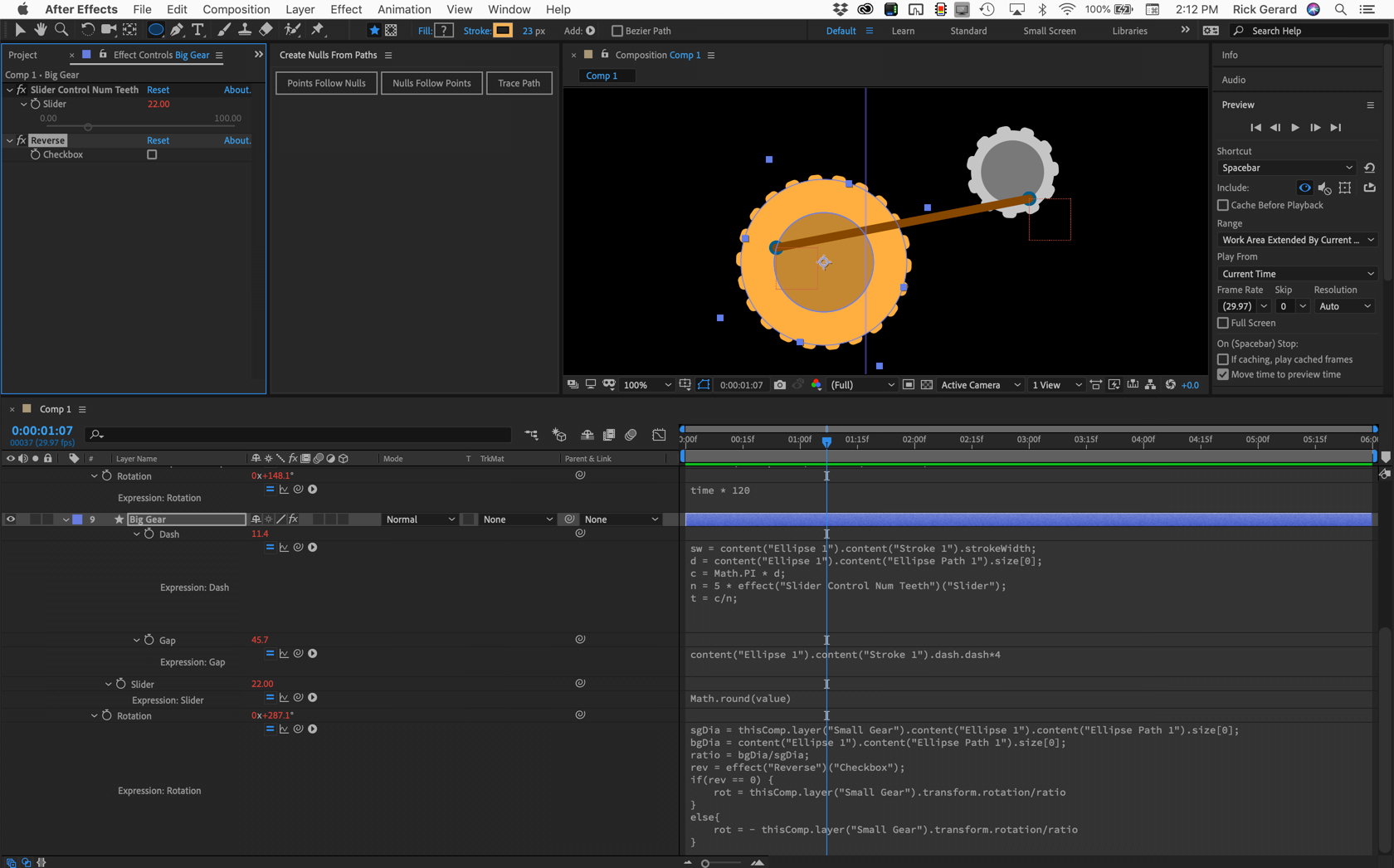
If the gears are turning as they would if they were touching you get some very odd movement in the connecting rod. If you change the size of the big wheel to match the size of the small wheel they will both rotate at the same speed and as long as they both rotate in the same direction and the angles match the shaft looks pretty normal.
I don't have a preset that would connect a crankshaft from one rotating object to another rotating object so that the first rotating object was driving the second. It would take some figuring, but it could be done. Then if the ratio between the size of each object was right you could get one gear to make the other one rotate continuously in one direction. If the ratio changes one gear rotating in one direction would cause the other gear to rotate back and forth. If that ratio changed the other so that the driving gear was larger than the driven gear the connection would fail or the crankshaft would have to stretch and compress as the larger gear tried to rotate the smaller one.
If I knew exactly what kind of motion the OP was trying to achieve I could come up with a solution. If the OP wants to just fake it and lets the laws of physics go out the window then adjusting the size of the paths in this sample comp and fiddling with the speed ratio between the two gears can pull off the effect.
NOTE: If your browser adds a .txt extension to the AEP file just delete it and it should open in the 2019 version of AE.
And I have to agree with Dave Merchant, if you are going to hang a bunch of 2D objects together in a bunch of odd ways the money you spend on Newton will be money well spent. Someday maybe they will release a 3D version...
Copy link to clipboard
Copied
First of all, I would like to thank everyone who answered me.
The solution you suggested, Rick, is perfect and really suitable for me.
I'll take a look at the individual expressions to get an even better understanding of the composition.
Thanks again for the great help! I really appreciate your effort.

 AdChoices